Search the documentation
Enter at least 2 characters
Enter at least 2 characters
 |
CAE Fidesys 9.0 Documentation |
When creating a finite element model, it is possible to define the desired local coordinate systems. Several coordinate systems can be defined in CAE Fidesys, each of which is assigned its own identification number (ID).
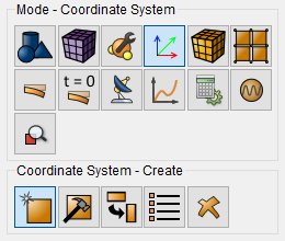
To create a new coordinate system, go to Mode - Coordinate Systems, Coordinate Systems - Create.
Specify:
Direction entities 1 and 2 together form the XoY plane in the new CS:
Direction entities 1 and 2 are specified as:
NOTE: For calculations taking into account cyclic symmetry, it will be sufficient to set the Cartesian coordinate system. In fact, for correct calculation the Z axis direction and the origin point are required.
The command to set a new coordinate system is given below:
create cs [[id] <ID>] [name <name>] [type {cartesian|cylindrical|spherical}]
origin {<coordX> <coordY> <coordZ>|node <ID>|vertex <ID>} dir1
{<coordX> <coordY> <coordZ>|node <ID>|vertex <ID>} dir2
{<coordX> <coordY> <coordZ>|node <ID>|vertex <ID>}
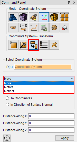
Previously created LSCs can be transformed using the following actions:
Using LCS for blocks: If material properties are defined based on coordinates, they will be calculated using the selected LCS. In the case of a block with a multilayer shell, this CS will be used to orient the elements – the axis in each element will be obtained by projecting this CS onto each element, the axis is perpendicular to the axis and lies in the plane of the element, the axis is perpendicular to the plane of the element.
Using the LCS for loads: If loads are defined based on coordinates, they will be calculated using the selected LCS.
A special case of the application of LSCs to loads is the application of pressure. The direction of pressure is always determined by the geometry of the surface to which it is applied. But for some tasks, it is necessary to be able to specify the law of change of the amplitude of this pressure from the coordinate. To do this, you need to create a Pressure and LSC load, then assign a coordinate system to this load and define a formula dependence for it based on the coordinate system in the GU Dependence on Time and/or coordinates widget.
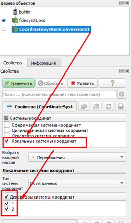
Using the Coordinate Systems – Local Coordinate Systems filter, you can use local coordinate systems created in the calculation in postprocessing. Coordinate systems are transferred using the IDs assigned in the preprocessor.
Go to the command bar (Mode - Coordinate Systems, Coordinate Systems - Create).
Specify:
Click Apply.
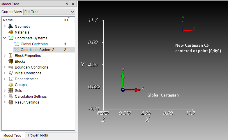
As a result, a new Cartesian CS appeared with the center at a point with coordinates (10;10;10) and axes parallel to the axes of the global CS.
There are several ways to use CS:
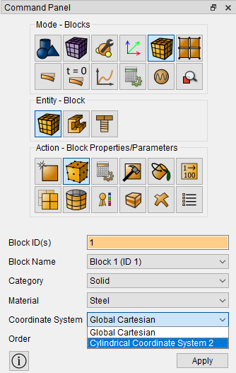
1. As the coordinate system of the block. In this case, this CS will be used for property dependencies, if they are set from coordinates.
In the case of a block with a multilayer shell, this SC will be used to orient the elements – the X axis in each element will be obtained by projecting this CS onto each element, the Y axis is perpendicular to the X axis and lies in the plane of the element, the Z axis is perpendicular to the plane of the element.
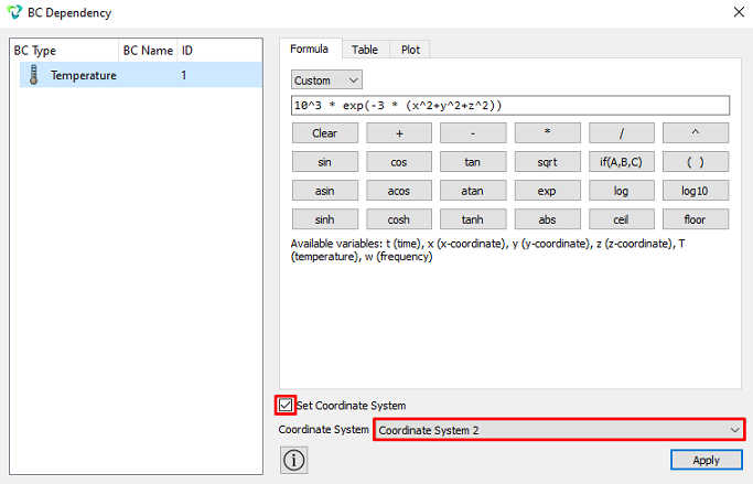
2. The applied boundary conditions and loads can be set by any of the created CS. In this case, the axes of the selected CS will be used for the axes of these boundary conditions.
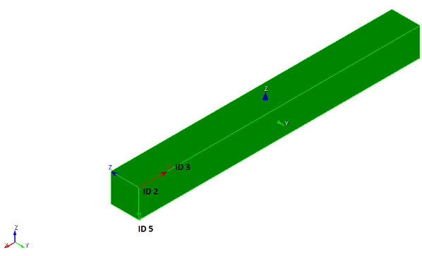
A carbon steel brick measuring 1×1×10 m is set in the center of the global CS:
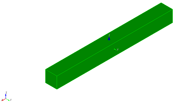
A Cartesian LCS was created at vertex ID 2 with the directions of the X and Y axes to vertices ID 3 and 5, respectively:
The temperature is set, concentrated in the center of coordinates, using the dependence of the temperature load, the temperature load is linked to the LCS:
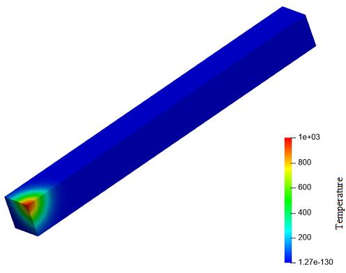
Thermal fields after 1 second of heating: