Search the documentation
Enter at least 2 characters
Enter at least 2 characters
 |
CAE Fidesys 9.0 Documentation |
A second converter for Ansys CDB files has been added (CDB II). Now, when using File – Import – and selecting the *.cdb format, you can choose between available converter options.
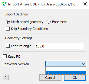
I – the CDB converter from previous versions.
II – the new converter developed for version 8.0.
The CDB II Converter expands the list of supported surface loads and analysis types. It uses a different approach to data processing and serves as an alternative to the existing Ansys CDB I converter.
| Analysis Name | Ansys Analysis Command | CAE Fidesys Conversion Result |
| Static Analysis | Antype,Static | Static Calculation |
| Modal Analysis | Antype,Modal | Modal Analysis |
| Harmonic (Frequency) Analysis | Antype, Harmic | Frequency Analysis |
| Spectral Analysis | Antype, Spectr | Spectral Analysis |
| Buckling Analysis | Antype, Buckle | Buckling Calculation |
| Element Type | Ansys Element Name | CAE Fidesys Conversion Result |
| Solid Element | solid185 | First-order solid body Node count and corresponding element type: 4: tetra4 5: pyr5 6: wedge 6 8: hex8 |
| Solid Element | solid186 | Second-order solid body Node count and corresponding element type: 10: tetra10 13: pyr13 15: wedge15 20: hex20 |
| Solid Element | solid187 | Second-order solid body Node count and corresponding element type: 10: tetra10 |
| Shell Element | shell181 | First-order shell Node count and corresponding element type: 3: mitc3 4: mitc4 |
| Shell Element | shell281 | Second-order shell Node count and corresponding element type: 3: mitc3 4: mitc4 |
| Beam Element | beam188 | First-order beam Node count and corresponding element type: 2: beam 2 |
| Beam Element | beam 189 | Second-order beam Node count and corresponding element type: 3: beam3 |
| Linear Spring | combin14 | Spring (type: linear spring) |
| Zero-Length Spring | combin14 | Boundary condition: DOF constraint with defined stiffness |
| Combined spring | combin40 | Spring (type: combined spring) |
| Lumped Mass Element | mass21 | Lumped Mass |
| BC Name | APDL Command in Ansys | CAE Fidesys Conversion Result |
| Displacements | D | Перемещения (список сущностей - узлы ) |
| Nodal Forces and Moments | F | Force, Moment (entity list – Node) |
| Gravity, Acceleration | ACEL | Gravity (entity list – Global) |
| Angular Velocity | CGOMEGA | Angular Velocity (entity list – Global) |
| Angular Acceleration | DCGOMG | Angular Acceleration (entity list – Global) |
| DOF Coupling (CP) | CP | Degree-of-Freedom Constraint |
| DOF Coupling (CE) | CE | Distance Constraint between entities |
| Pressure | SFERBLOCK | Pressure (entity list – triangle, quadrilateral) |
| Ansys Contact Type | CAE Fidesys Conversion Result |
| Standard - Rough | General contact type |
Bonded:
|
Tied contact type |
|
Tied Normal contact type |
|
Penalty |
| Multipoint constraint (MPC) | MPC |
| Property Name | Ansys Property Name | CAE Fidesys Conversion Result |
| Linear elastic isotropic material (Young’s modulus, Poisson’s ratio) | Linear Isotropic Material Properties(EX,PRXY) | Isotropic Material (Young’s modulus, Poisson’s ratio) |
| Mass density | Density | Density |
| Thermal expansion coefficient | Isotropic thermal Secant Coefficient | Thermal expansion coefficient |