Search the documentation
Enter at least 2 characters
Enter at least 2 characters
 |
CAE Fidesys 9.0 Documentation |
In CAE Fidesys 8.0, the Nastran BDF (*.bdf) converter has been completely redesigned. The updated version expands the list of supported analysis types, enables the import of materials and property blocks (such as beam and shell cross-sections), and provides a broader range of supported boundary conditions
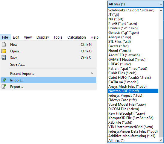
The converter can be accessed via: Menu – File– Import - Nastran BDF (*.bdf).
| Element Type | Nastran Element | CAE Fidesys Conversion Result |
| Solid Element | CTETRA | Solid body Node count and element type/order: 4: TETRA4 (1) 10: TETRA10 (2) |
| Solid Element | CHEXA | Solid body Node count and element type/order: 6: WEDGE6 (1) 8: HEX8 (2) 15: WEDGE15 (2) 20: HEX20 (2) |
| Solid Element | CPYRAM | Solid body Node count and element type/order: 5: PYR5 (1) 13: PYR13 (2) |
| Solid Element | CPENTA | Solid body Node count and element type/order: : 6: WEDGE6(1) 15: WEDGE15 (2) |
| Shell Element | CQUAD | Shell Node count and element type/order: 4: MITC4 (1) 8: MITC8 (2) |
| Shell Element | CTRIA | Shell Node count and element type/order: 3: MITC3 (1) 6: MITC6 (2) |
| Shell Element (Shear Panel) | CSHEAR | Shell Node count and element type/order: 4: MITC4 (1) |
| Beam Element | CBEAM | Beam Node count and element type/order: 2: BEAM2b (1) 3: BEAM3b (2) |
| Beam Element | CBAR | Beam Node count and element type/order: 2: BAR2 (1) 3: BAR3 (2) |
| Rod Element | CROD | Rod (Block Beam + ‘type’: ‘rod’) Node count and element type/order: 2: BEAM2b (1) |
| Zero-length Spring | CBUSH (single-point spring) | Three springs created (along X, Y, Z axes), each assigned the corresponding properties |
| Zero-length Spring | CELAS2 (single-point spring) | Three springs created (along X, Y, Z axes), each assigned the corresponding properties |
| Linear Spring | CBUSH (two-point spring) | Spring created as a distance constraint (RBE2); only stiffness is transferred |
| Linear Spring | CELAS2 (two-point spring) | Spring created as a distance constraint (RBE2); only stiffness is transferred |
| Lumped Mass Element | CONM2 | Lumped Mass Node count and element type/order: 1: LUMPMASS (1) |
| BC Name | Nastran Command | CAE Fidesys Conversion Result |
| Displacements | SPC, SPC1 | Displacements (Entity list – Nodes) |
| Nodal Forces and Moments | FORCE, MOMENT | Force, Moment (Entity list – Node) |
| Centrifugal Force | RFORCE | Angular Velocity (Entity list – Global) |
| Gravity | GRAV | Gravity (Entity list – Global) |
| DOF-based Constraint | RBE1 | Degree-of-Freedom Constraint |
| Distance-based Constraint | RBE2 | Distance Constraint |
| Interpolation Constraint | RBE3 | Interpolation Constraint |
| Nastran Contact Type | CAE Fidesys Conversion Result |
| General | General contact type (contact method: auto) |
| Glue | Tied contact type (contact method: auto) |
| Property Names | Nastran Material Type | CAE Fidesys Conversion Result |
| - Poisson’s ratio - Young’s modulus - Density - Damping coefficient |
MAT1 | Isotropic Material: - Poisson’s ratio - Young’s modulus - Density - Damping coefficient |
| - Density - Poisson’s ratio - Young’s modulus |
MAT8 | - Density - Poisson’s ratio - Young’s modulus |
| - Density - Speed of sound - Damping coefficient - Shear modulus |
MAT10 | - Density - Speed of sound - Damping coefficient - Shear modulus |
Support for the conversion of Cartesian, cylindrical, and spherical coordinate systems has also been implemented.