Search the documentation
Enter at least 2 characters
Enter at least 2 characters
 |
CAE Fidesys 9.0 Documentation |
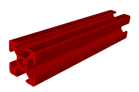
Version 8.0 introduces the ability to use custom sections in calculations. To create a custom section, you must import a section file in *.beam format.
Important: Be careful with the dimensions in which you import or create a section.
Let's look at creating a custom section using a profile as an example.
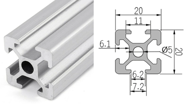
Important: The Plane block must lie in the XY plane (the Z plane). The order of the elements affects the number of nodes and elements in the section and does not conflict with the order of the Beam or Rod block.
To create geometry and generate a mesh, run the following commands in the CAE Fidesys preprocessor:
reset
create surface rectangle width 4.5 zplane
Surface 1 copy move x {10-2.25} y {10-2.25}
Surface 1 copy move x {10-2.25} y -{10-2.25}
Surface 1 copy move x -{10-2.25} y -{10-2.25}
move Surface 1 x -{10-2.25} y {10-2.25} include_merged
create surface rectangle width 1.5 height 20 zplane
create surface rectangle width 20 height 1.5 zplane
unite surface 5 6
rotate Surface 7 angle 45 about Z include_merged
create surface rectangle width {3.9*2} zplane
Vertex 2 copy move x {(20-7.2)/2}
Vertex 2 copy move y {-(20-7.2)/2}
Vertex 33 copy move y -0.5
Vertex 34 copy move x .5
Vertex 35 copy move x 0.5
Vertex 36 copy move y -0.5
Vertex 37 copy move y -1
Vertex 38 copy move x 1
Vertex 40 copy move y 5.4
create surface vertex 2 34 36 38 40 41 39 37 35 33 ####Geometry - surface - create - vertex list
tweak vertex 34 33 fillet radius .25 ####Geometry - Vertex - Edit - Tweak - Fillet Radius
tweak vertex 35 36 fillet radius .25
tweak vertex 37 38 fillet radius .25
tweak vertex 40 39 fillet radius .5
Surface 9 copy rotate 90 about z repeat 3
unite surface all
create surface circle radius 2.5 zplane
subtract surface 14 from surface 13
tweak vertex 2 5 15 12 fillet radius 1.5
tweak vertex 111 110 105 104 99 98 117 116 fillet radius .25
tweak vertex 115 118 119 114 113 112 109 108 107 102 106 103 101 100 97 120 fillet radius 2
surface 15 size auto factor 2
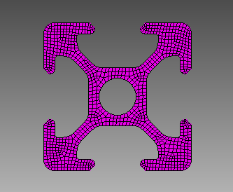
mesh surface 15
1. Create a block.
On the command bar, select the block management module (Mode - Blocks, Entity - Block, Action - Add).

Specify the following parameters:
Block ID: 1;
Entity List: Surface;
Entity ID(s): 15.
Click Apply.
2. Set the block parameters.
On the command bar, select the block management module (Mode - Blocks, Entity - Block, Action - Block properties/parameters).

1Set the following parameters:
Block ID(s): 1;
Category: Plane;
Coordinate System: Global Cartesian;
Order: 1.
Click Apply.
In this case, you don't need to specify a material, since the element order only affects the section mesh. If necessary, scale the model to the desired system.
3. Then export the section.
On the command bar, select the block management module (Mode - Blocks, Entity - Custom beam sections).
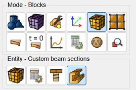
Specify the following parameters:
Export;
Block ID(s): 1;
File name: example;
If Section Exists: Overwrite.
Click Save.
By default, the file will be saved in the CAE Fidesys system folder (C:\Users\Name\Documents\CAE-Fidesys-9.0).
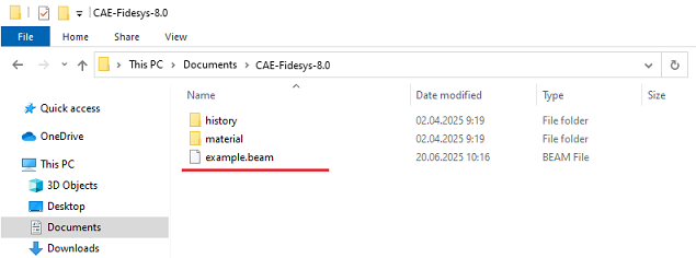
To continue using the custom section, in the Beams or Rods properties widget in the section profile, select Imported Sections from the available sections, and then select the previously created file.
4. Below, we'll demonstrate how to use this file using an example. First, we'll create the geometry, mesh, and define a material and block. To do this, enter the following into the command line:
reset
create curve location 0 0 0 location 0 0 100
curve 1 interval 10 preview
curve 1 scheme bias
curve 1 interval 10 preview
curve 1 scheme bias
mesh curve 1
create material 1 from 'Steel'
set duplicate block elements off
block 1 add curve 1
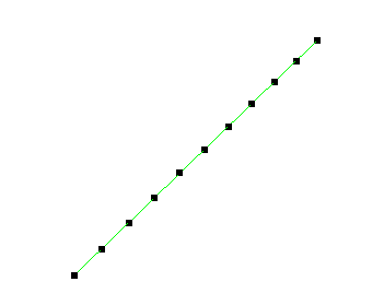
5. Set the parameters for the block using the previously created file.
On the command bar, select the block management module (Mode - Blocks, Entity - Block, Action - Block properties/parameters).
Set the following parameters:
Block ID(s): 1;
Category: Beam;
Material: Steel;
Coordinate System: Global Cartesian;
Order: 1.
Set the beam properties by clicking the  button.
Set the following parameters:
Section Profile: Imported Sections;
Available Sections: example.beam.
Click Apply.
Close the Set Beam Properties window.
Click Apply.
Display the 3D view of the model. To do this, click Show 3D View of Model on the toolbar. This will display the 3D view of the model.