Search the documentation
Enter at least 2 characters
Enter at least 2 characters
 |
CAE Fidesys 9.0 Documentation |
The problem of finding the maximum Mises voltage after applying the Element Solution filter is solved.
1.Create a parallelepiped.
On the command bar, select the module for constructing volume geometry (Mode - Geometry, Entity - Volume, Action - Create).

From the list of geometric primitives, select Brick.
Set the following parameters:
X (width): 1000;
Y (height): 100;
Z (depth): 100.
Click Apply.
1. Set the approximate size of the elements.
On the command bar, select the volume mesh module (Mode — Mesh, Entity – Volume, Action – Intervals).
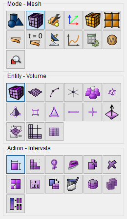
Select from the list Approximate Size.
Set the following parameters:
Select Volumes: 1 (or the command all);
Approximate Size: 5.
Click Apply.
2. On the command bar, select the volume mesh module (Mode – Mesh, Entity – Volume, Action – Mesh).
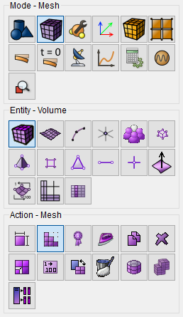
Set the following parameters:
In the drop-down list, select: Map;
Select Volumes: 1 (or the command all).
Click Apply Scheme.
Click Mesh.
1. Specify the material.
In the command bar, select the module for specifying material properties (Mode - Material, Entity - Materials Management).

Specify the name of the material "Material1".
In the window on the left, go to the Elasticity section and drag the label Isotropic Material in column Material Properties.
Set the following parameters:
Young's modulus: 2e+11;
Poisson ratio: 0.
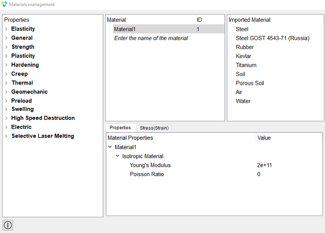
Click Apply.
Close the window Materials management.
2. Create a block of one material type.
On the command bar, select the block management module (Mode — Blocks, Entity — Block, Action — Add).

Set the following parameters:
Block ID: 1;
Entity List: Volume;
Entity ID(s): 1 (or the command all).
Click Apply.
3. Set the block parameters.
On the command bar, select the block management module (Mode - Blocks, Entity - Block, Action - Block properties/parameters).

Set the following parameters:
Block ID(s): 1;
Category: Solid;
Material: Material1;
Coordinate System: Global Cartesian;
Order: 1.
Click Apply.
1. Fix the end of the parallelepiped along the X, Y, Z axis.
On the command panel, select the boundary conditions module (Mode — Boundary Conditions, Entity — Displacement, Action — Create).

Set the following parameters:
Entity List: Surface;
Entity ID(s): 4;
Degrees of Freedom: X, Y, Z.
Click Apply.
2. Apply pressure to the upper face of the parallelepiped.
On the command panel, select the boundary conditions module (Mode — Boundary Conditions, Entity — Pressure, Action — Create).
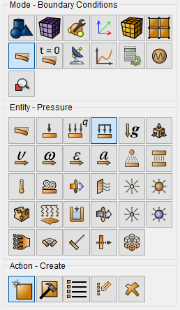
Set the following parameters:
Entity List: Surface;
Entity ID(s): 5;
Value: 1000.
Click Apply.
1. On the command bar, select the calculation settings module (Mode - Calculation, Calculation - Static, Static - General).

Select:
Dimension: 3D;
Model: Elasticity.
Click Apply.
Click Start Calculation.
1. Open the file with the results. There are three ways to do that.
Click Ctrl+E.
From the main menu, select Calculation. Click Open Results.
Select Results on Command Panel (Mode - Results). Click Open results.

The FidesysViewer window will appear, in which you can view the calculation results.
In the standard line, select Filters → Alphabetical → Element Solution.
In the properties panel, select only Process All Arrays.
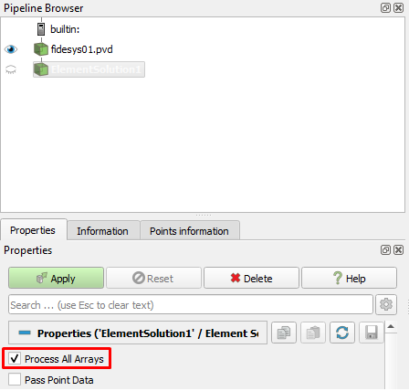
Click Apply.
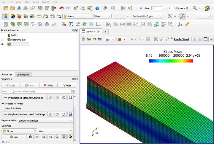
In the upper panel, select the calculation result data to display. From the first drop-down list, select Stress, from the second – Mises from the third – Surface With Edges.

After applying the settings, the following picture should be displayed:
Geometry creating, meshing, setting boundary conditions and materials can be performed using the console interface. Below is a link to the program code that allows you to perform the steps described above manual, you only need to specify the full path and name.