Search the documentation
Enter at least 2 characters
Enter at least 2 characters
 |
CAE Fidesys 9.0 Documentation |
An example of mines formation is considered. There is a total volume of soil, from which volumes are removed in a few steps, simulating the process of formations mines. Gravity affects all volumes.
There will consider 4 volumes for mines, which will be sequentially deleted in 5 calculation steps.
1. Enter the command at the command line using APREPRO:
#{num = 4}
{num} is a variable for the number of sequentially removed volumes in the mine.
2. Creation of the main soil volume.
On the command bar, select the module for constructing volume geometry (Mode - Geometry, Entity - Volume, Action - Create).

From the list of geometric primitives, select Brick.
Set the following parameters:
X (Width): {num+1};
Y (height): 10;
Z (depth): 10.
Click Apply.
3. Cylinder creation.
On the command bar, select the module for constructing volume geometry (Mode - Geometry, Entity - Volume, Action - Create).
From the list of geometric primitives, select Cylinder.
Set the following parameters:
Height: {num};
Circular;
Radius: 1.
Click Apply.
4. Rotate the cylinder 90 degrees around the Y axis.
On the command bar, select the module for constructing volume geometry (Mode - Geometry, Entity - Volume, Action - Transform).
From the list select Rotate.
Set the following parameters:
Volume ID(s): 2;
Angle: 90;
Rotate About: Y-Axis.
Click Apply.
5. Move the cylinder.
On the command bar, select the module for constructing volume geometry (Mode - Geometry, Entity - Volume, Action - Transform).
From the list select Move.
Set the following parameters:
Volume ID(s): 2;
Select Method: Distance;
X Distance: 0.5.
Click Apply.
6. Subtract the cylinder from the brick.
On the command bar, select the module for constructing volume geometry (Mode - Geometry, Entity - Volume, Action - Boolean).
From the list select Subtract.
Set the following parameters:
A Volume ID(s): 1;
B Volume ID(s): 2.
Click Apply.
7. Enter the command at the command line to correct volumes numeration compress all.
8. Create 4 cylinders using loop (aprepro). The height of each cylinder 1 and radius 1. Turn the cylinders 90 degrees. Move each cylinder a distance {i-num/2}. Enter the commands at the command line:
#{i = 1}
#{Loop(num)}  цикл
create Cylinder height 1 radius 1
rotate Volume {i+1} angle 90  about Y
move vol {i+1} x {i-num/2}
#{i++}
#{EndLoop}
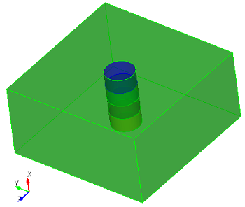
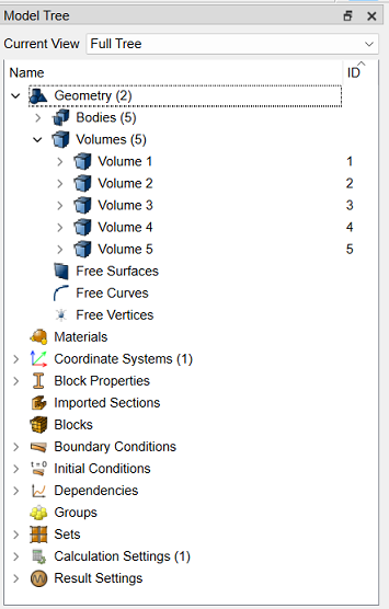
In the Model Tree on the left side you can see that 5 volumes have been created.
9. Merge all the volumes received. Enter the commands at the command line:
imprint all
merge all
Enter the command at the command line:
mesh vol all
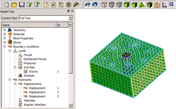
As a result, a finite element mesh is constructed on the model:
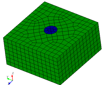
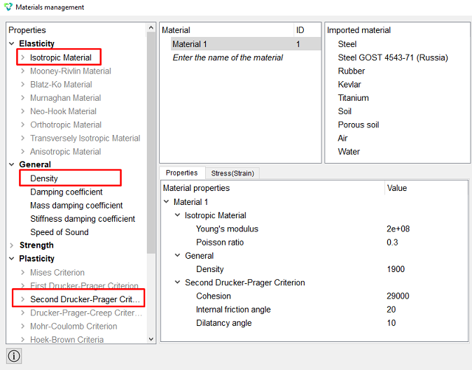
In the command bar, select the module for specifying material properties (Mode - Material, Entity - Materials Management).

Specify the name of the material Material 1.
Specify the following parameters:
Elasticity - Isotropic Material - Young's modulus E = 2e+08;
Elasticity - Isotropic Material - Poisson ratio ν = 0.3;
General - Density ρ = 1900;
Cohesion = 29000;
Plasticity - Second Drucker-Prager Criterion - Internal friction angle = 20;
Plasticity - Second Drucker-Prager Criterion - Dilatancy angle = 10.
Click Apply.
Close the Materials management window.
1. Using a loop, create 5 blocks. Enter the commands at the command line:
block 1 vol 1
#{i = 1}
#{Loop(num)}
block {i+1} vol {num+2-i}
#{i++}
#{EndLoop}
Thus, 5 blocks were created.
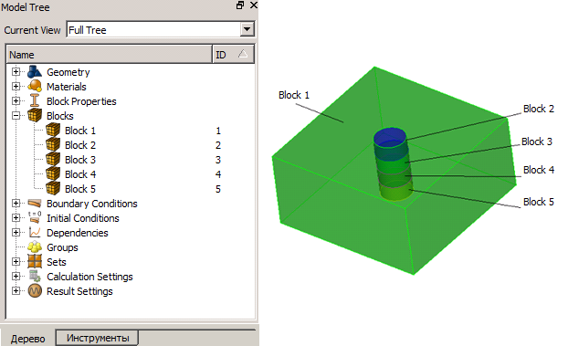
2. Set the block parameters.
On the command bar, select the block management module (Mode - Blocks, Entity - Block, Action - Block properties/parameters).

Set the following parameters:
Block ID(s): all;
Category: Solid;
Materials: Material 1;
Coordinate System: Global Cartesian;
Order: 2.
Click Apply.
1. Fix surface 2 along the Z-axis.
On the command panel, select the boundary conditions module (Mode - Boundary Conditions, Entity - Displacement, Action - Create).

Set the following parameters:
Entity List: Surface;
Entity ID(s): 2;
Degrees Of Freedom: Z.
Click Apply.
2. Fix surfaces 3 and 5 along the Y-axis.
Set the following parameters:
Entity List: Surface;
Entity ID(s): 3 5;
Degrees Of Freedom: Y.
Click Apply.
3. Fix surfaces 4 and 8 along the X-axis.
Set the following parameters:
Entity List: Surface;
Entity ID(s): 4 8;
Degrees Of Freedom: X.
Click Apply.
4. Create gravity.
On the command panel, select the boundary conditions module (Mode - Boundary Conditions, Entity - Gravity, Action - Create).
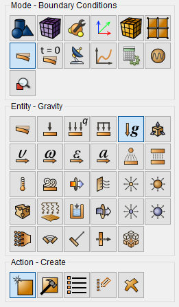
Set the following parameters:
Entity List: Global;
Directions Z: -9.81.
Click Apply.
All boundary conditions can be viewed in the Model Tree on the left side.
1. On the command bar, select the calculation settings module (Mode — Calculation Settings, Calculation Settings — Static, Static — General).

Select:
Dimensions: 3D;
Model: Elasticity;
Set static load steps count: 5.
Click the button opposite the field with setting
the number of loading steps. In the appeared Settings of loading steps
window, assign active steps to blocks.
opposite the field with setting
the number of loading steps. In the appeared Settings of loading steps
window, assign active steps to blocks.
Block 1 (main soil volume) is involved at all calculation steps. Highlight Block 1 in the left column and enter all in the Block tab on the right. Click Apply.
Block 2 (upper volume) is involved at the first calculation step. Next, this volume is removed. Highlight Block 2 in the left column and enter 1 in the Block tab on the right. Click Apply.
Block 3 (second volume) is involved at the first and second calculation steps. Next, this volume is removed. Highlight Block 3 in the left column and enter 1 2 (separated by space) in the Block tab on the right. Click Apply.
Block 4 (third volume) is involved at the 1, 2 and 3 calculation steps. Next, this volume is removed. Highlight Block 3 in the left column and enter 1 2 3 (separated by space) in the Block tab on the right. Click Apply.
Block 5 (fourth volume) is involved at the 1, 2, 3 and 4 calculation steps. Next, this volume is removed. Highlight Block 3 in the left column and enter 1 2 3 4 (separated by space) in the Block tab on the right. Click Apply.
Thus, the fields should be filled as follows:

Close the Settings of loading steps window.
The same actions can be carried out using a loop.Enter the commands at the command line:
static steps {num+1}
#{i = 1}
#{Loop(num)}
block {i+1} step 1 to {i}
#{i++}
#{EndLoop}
On Command Panel click Apply and Start Calculation.
2. In a pop-up window select a folder to save the result and enter the file name.
3. In the case of a successful calculation, the console displays the message: Calculation finished successfully at "date" "time".
1. Open the file with the results. There are three ways to do that.
Click Ctrl+E.
From the main menu, select Calculation. Click Open Results.
Select Results on Command Panel (Mode - Results). Click Open results.

View the calculation results in the FidesysViewer window.
In the Toolbar, set to display the first calculation step.

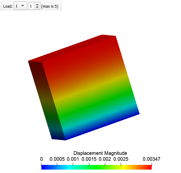
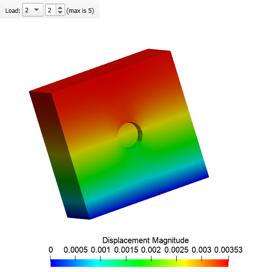
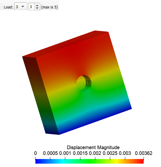
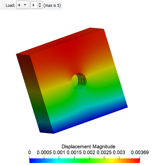
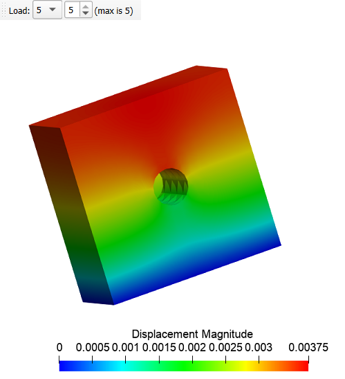
Display on the model Displacements (Magnitude).

Next, switching steps from 1 to 5, display the process of removing output in the calculation process.
Geometry creating, meshing, setting boundary conditions and materials can be performed using the console interface. Below is a link to the program code that allows you to perform the steps described above manual, you only need to specify the full path and name.