Search the documentation
Enter at least 2 characters
Enter at least 2 characters
 |
CAE Fidesys 9.0 Documentation |
1. Create a circle.
On the command bar, select the module for constructing surface geometry (Mode - Geometry, Entity - Surface, Action - Create).

From the list of geometric primitives, select Circle.
Set the following parameters:
Specify Circle Using: Radius;
Radius: 100;
Plane: ZPlane.
Click Apply.
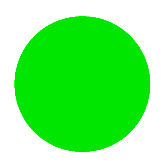
2. Create a circle.
On the command bar, select the module for constructing surface geometry (Mode - Geometry, Entity - Surface, Action - Create).
From the list of geometric primitives, select Circle.
Set the following parameters:
Specify Circle Using: Radius;
Radius: 200;
Plane: ZPlane.
Click Apply.
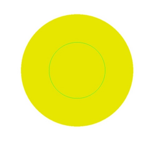
3. Subtract the circle.
On the command bar, select the module for constructing surface geometry (Mode - Geometry, Entity - Surface, Action - Boolean).
From the list of geometric primitives, select Subtract.
Set the following parameters:
A Surface ID(s): 2;
B Surface ID(s): 1.
Click Apply.

4. Cut the surface using the ZX plane.
On the command bar, select the module for constructing surface geometry (Mode - Geometry, Entity - Surface, Action - Webcut).
From the pop-up list Coordinate Plane.
Specify the required parameters:
Body ID(s): all;
Plane: ZX;
Offset Value: 0.
Click Apply.

5. Cut the surface using the YZ plane.
On the command bar, select the module for constructing surface geometry (Mode - Geometry, Entity - Surface, Action - Webcut).
From the pop-up list Coordinate Plane.
Specify the required parameters:
Body ID(s): all;
Plane: YZ;
Offset Value: 0.
Click Apply.

6. Delete surfaces 6, 7, 9.
On the command bar, select the module for constructing surface geometry (Mode - Geometry, Entity - Surface, Action - Delete).
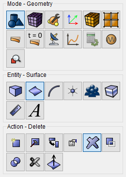
Set the following parameters:
Surface ID(s): 6 7 9.
Click Apply.

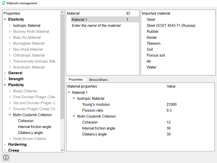
1. In the command bar, select the module for specifying material properties (Mode — Material, Entity — Materials Management).

Enter the name of the material Material 1.
In the Elasticity list transfer property column, drag from the left side, column labeled Isotropic Material to the Material Properties column.
Set the following parameters:
Young's modulus: 21000;
Poisson ratio: 0.3.
In the properties column, open the Plasticity list, drag the Mohr-Coulomb Criterion label from the left column to the Material Properties column.
Set the following parameters:
Cohesion: 12;
Internal friction angle: 30;
Click Apply.
Close the Materials management window.
2. Create a block.
On the command bar, select the block management module (Mode — Blocks, Entity — Block, Action — Add).

Set the following parameters:
Block ID: 1;
Entity List: Surface;
Entity ID(s): all.
Click Apply.
3. Set the block parameters.
On the command bar, select the block management module (Mode - Blocks, Entity - Block, Action - Block properties/parameters).

Set the following parameters:
Block ID(s): 1;
Category: Plane;
Material: Material 1;
Coordinate System: Global Cartesian;
Order: 2.
Click Apply.
1. Fix one Y curve.
On the command panel, select the boundary conditions module (Mode — Boundary Conditions, Entity — Displacement, Action — Create).

Set the following parameters:
Entity List: Curve;
Entity ID(s): 8;
Degrees of Freedom: Y.
Click Apply.
2. Fix one curve in X.
On the command panel, select the boundary conditions module (Mode — Boundary Conditions, Entity — Displacement, Action — Create).
Set the following parameters:
Entity List: Curve;
Entity ID(s): 18;
Degrees of Freedom: X.
Click Apply.
3. Set the pressure.
On the command panel, select the boundary conditions module (Mode — Boundary Conditions, Entity — Pressure, Action — Create).
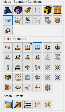
Set the following parameters:
Entity List: Curve;
Entity ID(s): 19;
Value: 12.
Click Apply.
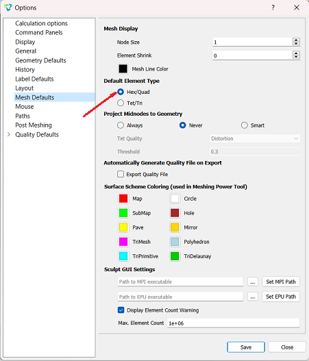
To build a hexahedral mesh, set the element type in the mesh settings by default, to do this, on the top panel select Tools - Options. Next, in the settings, find the “Mesh Defaults” section and choose element type - hex, then click "Save".
1. Specify the mesh construction scheme.
On the command bar, select the mesh module (Mode - Mesh, Entity
- Curve, Action - Mesh).
Set the following parameters:
Select Curves: 19 20;
Select the mesh construction method: Equal;
Set the flag: Interval;
Interval: 20.
Click Apply Size.
2. Specify the mesh construction scheme.
On the command bar, select the mesh module (Mode - Mesh, Entity - Curve, Action - Mesh).
Set the following parameters:
Select Curves: 8 18;
Select the mesh construction method: Equal;
Set the flag: Approximate Size;
Approximate Size: 4.
Click Apply Size.
3. Specify the mesh construction scheme.
On the command bar, select the surface mesh module (Mode - Mesh, Entity - Surface, Action - Mesh).
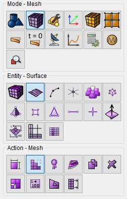
From the list of actions, select Automatically Calculate.
Set the following parameters:
Select Surfaces: all.
Click Mesh.
1. Specify the type of task you want to solve.
On the command bar, select the calculation settings module (Mode — Calculation Settings, Settings Calculation — Static, Static — General).

Set the following parameters:
Dimensions: 2D;
Plane State: Plane Strain;
Model: Elasticity, Plasticity;
Set Static Load Steps Count ;
Load Steps Count: 1;
Set Nonlinear Solver Options;
Start Load Substeps: 21;
Min Load Substeps: 20;
Max Load Substeps: 1000;
Max Iterations: 100;
Tolerance: 0.01;
Target Iterations: 5.
Click Apply.
Click Start Calculation.
2. In a pop-up window select a folder to save the result and enter the file name.
3. In the case of a successful calculation, the console displays the message: Calculation finished successfully at "date" "time".
1. Open the file with the results. There are three ways to do that.
Click Ctrl+E.
From the main menu, select Calculation. Click Open Results.
Select Results on Command Panel (Mode - Results). Click Open results.

The FidesysViewer window will appear, in which you can view the calculation results.
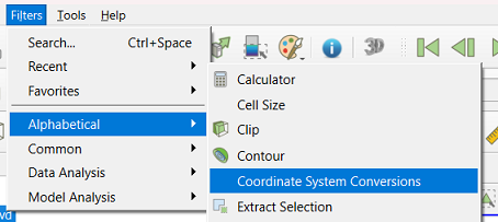
2. Go to cylindrical CS.
On the command bar, select Filters - Alphabetical — Coordinate System Conversions.
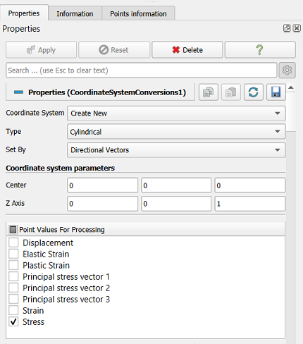
In Properties select:
Coordinate Systems: Create New;
Type: Cylindrical;
Point Values For Processing: Stress.
Click Apply.
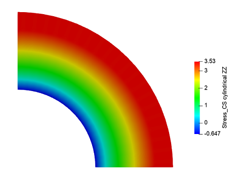
From the first drop-down list, select Stress_CS cylindrical, from the second - ZZ, from the third - Surface.

3. Plot stress graphs along the radius of the cylinder.
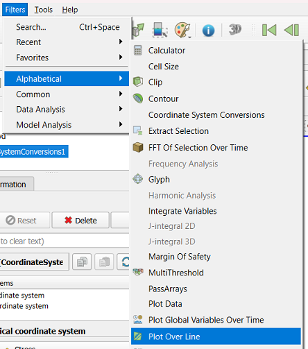
On the command bar, select Filters - Alphabetical - Plot Over Line.
 l; ]p
l; ]p
Click Apply.
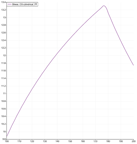
Display graph Stress_CS cylindrical_FF.
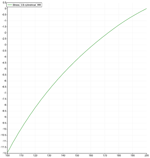
Display graph Stress_CS cylindrical_RR.
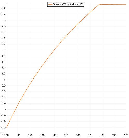
Display graph Stress_CS_cylindrical_ZZ.
Geometry creating, meshing, setting boundary conditions and materials can be performed using the console interface. Below is a link to the program code that allows you to perform the steps described above manual, you only need to specify the full path and name.