Search the documentation
Enter at least 2 characters
Enter at least 2 characters
 |
CAE Fidesys 9.0 Documentation |
This example demonstrates the possibility of calculating a model consisting of different types of elements without contact interaction. Also in the problem demonstrates the capabilities of the APREPRO programming language for working in CAE Fidesys, namely: assigning a variable and further working with her in the script; using a loop (analogous to for), if-else conditions and the continue operator.
APREPRO programming language - algebraic preprocessor for task finite element analysis parameters. APREPRO variables can be set and modified using the GUI.
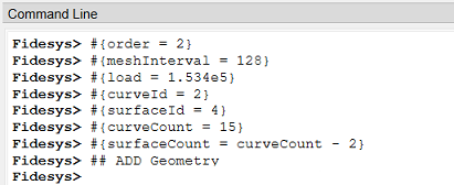
1. To set variables that will be used in further constructions and calculations, write in the command line:
#{order = 2}
#{meshInterval = 128}
#{load = 1.534e5}
#{curveId = 2}
#{surfaceId = 4}
#{curveCount = 15}
#{surfaceCount = curveCount - 2}
## ADD Geometry
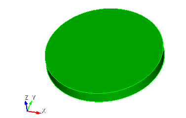
1. Create a cylinder.
On the command bar, select the module for constructing volume geometry (Mode - Geometry, Entity - Volume, Action - Create).

From the list of geometric primitives, select Cylinder.
Set the following parameters:
Height: 1;
Circular;
Radius: 5.
Click Apply.
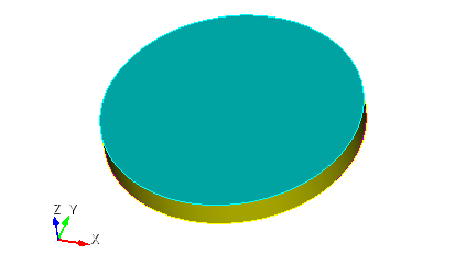
2. Create a cylindrical shell.
Get a cylindrical shell from a volumetric cylinder.
On the command bar, select the module for constructing volume geometry (Mode - Geometry, Entity - Volume, Action - Delete).
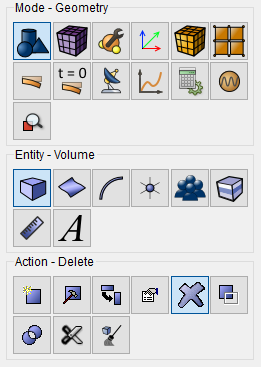
Set the following parameters:
Volume ID(s): 1;
Tick the box: Keep Lower Geometry.
Click Apply.
3. Delete the side planes.
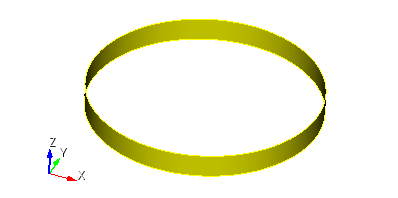
On the command bar, select the module for constructing surface geometry (Mode - Geometry, Entity - Surface, Action - Delete).
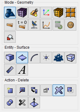
Set the following parameters:
Surface ID(s): 3 2.
Click Apply.
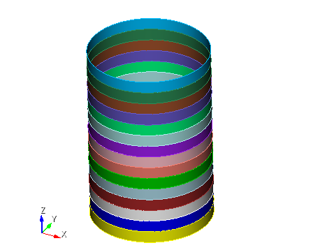
4. Create the cylinders.
Copy and move surfaces while maintaining all properties.
On the command bar, select the module for constructing surface geometry (Mode - Geometry, Entity - Surface, Action - Create).

From the pop-up list, select Copy and Transform.
Set the following parameters:
Surface ID(s): 1;
Tick the box: Transform Copied Surfaces;
Move;
Z: 1;
Repeat: 14;
Tick the box: Copy Mesh.
Click Apply.
5. Merge the geometric model.
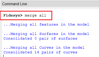
Enter the following command into the command line: merge all.
Click Apply.
1. Set the material.
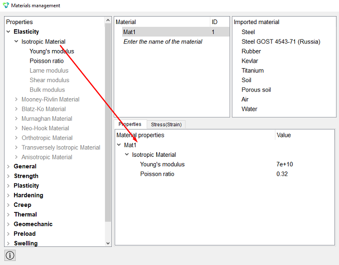
In the command bar, select the module for specifying material properties (Mode - Material, Entity - Material Management).

In the column "Material" enter the material nameMat1. Click Apply.
In the column "Material properties" select the created material, then drag the desired properties from the left column to it.
Drag properties for elasticity, selecting Isotropic Material. Please indicate them meaning:
Young's modulus: 7e+10;
Poisson ratio: 0.32.
Click Apply.
Close the Materials management window.
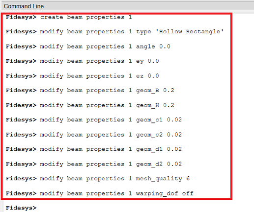
2. Set properties for the beam. Enter the following commands into the command line:
create beam properties 1
modify beam properties 1 type 'Hollow Rectangle'
modify beam properties 1 angle 0.0
modify beam properties 1 ey 0.0
modify beam properties 1 ez 0.0
modify beam properties 1 geom_B 0.2
modify beam properties 1 geom_H 0.2
modify beam properties 1 geom_c1 0.02
modify beam properties 1 geom_c2 0.02
modify beam properties 1 geom_d1 0.02
modify beam properties 1 geom_d2 0.02
modify beam properties 1 mesh_quality 6
modify beam properties 1 warping_dof off
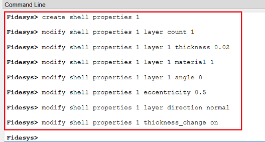
3. Set properties for the first shell. Type into the command line commands:
create shell properties 1
modify shell properties 1 layer count 1
modify shell properties 1 layer 1 thickness 0.02
modify shell properties 1 layer 1 material 1
modify shell properties 1 layer 1 angle 0
modify shell properties 1 eccentricity 0.5
modify shell properties 1 layer direction normal
modify shell properties 1 thickness_change on
4. Set properties for the second shell. Type into the command line commands:
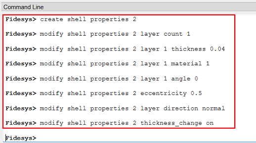
create shell properties 2
modify shell properties 2 layer count 1
modify shell properties 2 layer 1 thickness 0.04
modify shell properties 2 layer 1 material 1
modify shell properties 2 layer 1 angle 0
modify shell properties 2 eccentricity 0.5
modify shell properties 2 layer direction normal
modify shell properties 2 thickness_change on
5. Using a loop, assign beam properties to the first block and build mesh:
#{loop(curveCount)}
        #{if(curveId==4)}
                #{continue}
        #{else}
                curve {curveId}  interval {meshInterval}
                curve {curveId} scheme equal
                mesh curve {curveId}
                block 1 add curve {curveId}
        #{endif}
        #{curveId+= 2}
#{endloop}
block 1 material 1 cs 1 element beam order {order}
block 1 beam properties 1
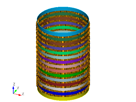
6. Using a loop, assign the properties of the first shell to the second block and build the mesh:
#{loop(surfaceCount)}
        surface {surfaceId} size auto factor 1
        mesh surface {surfaceId}
        block 2 add surface {surfaceId}
        #{surfaceId++}
#{endloop}
block 2 material 1 cs 1 element shell order {order}
block 2 shell properties 1
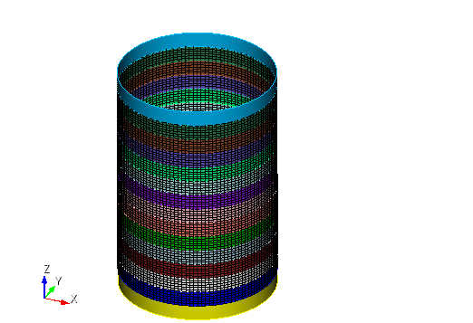
7. Using a loop, assign the properties of the second shell to the third block and build the mesh:
surface 1,17 size auto factor 1
mesh surface 1,17
block 3 add surface 1,17
block 3 material 1 cs 1 element shell order {order}
block 3 shell properties 2
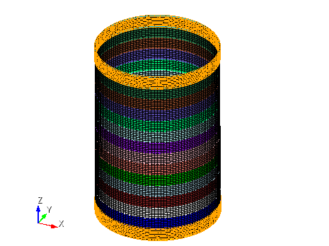
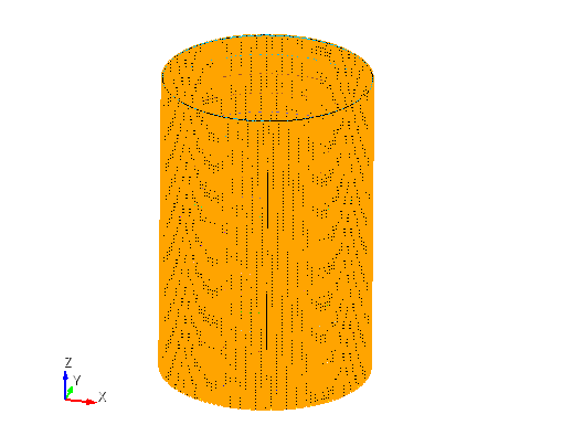
1. Apply pressure normal to the surface on all cylindrical surfaces.
On the command panel, select the boundary conditions module (Mode - Boundary Conditions, Entity - Pressure, Action - Create).
Set the following parameters:
Pressure Entity List: Surface;
Entity ID(s): all;
Magnitude Value: 500000;
Tick the box: Interpret Value As;
Tick the box: Use Pure Pressure.
Click Apply.
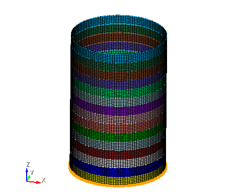
2. Secure one end of the model along all degrees of freedom.
On the command panel, select the boundary conditions module (Mode - Boundary Conditions, Entity - Displacement, Action - Create).

Set the following parameters:
Entity List: Curve;
Entity ID(s): 1;
Degrees Of Freedom: All;
DOF Value: 0.
Click Apply.
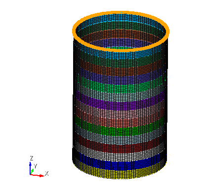
3. Secure the second end.
On the command panel, select the boundary conditions module (Mode - Boundary Conditions, Entity - Displacement, Action - Create).
Set the following parameters:
Entity List: Curve;
Entity ID(s): 32;
Degrees Of Freedom: Х-Translation Disp, Y-Translation Disp, X-Rotation Disp, Y-Rotation Disp, Z-Rotation Disp;
DOF Value: 0.
Click Apply.
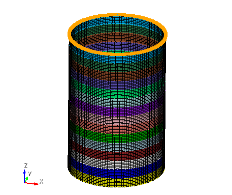
4. Apply compressive force to the second end.
On the command panel, select the boundary conditions module (Mode - Boundary Conditions, Entity - Force, Action - Create).
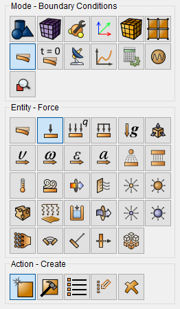
Set the following parameters:
Force Entity List: Curve;
Entity ID(s): 32;
Tick the box: Specify Using Vector;
Force Х Component: 0;
Force Y Component: 0;
Force Z Component: {-load/(meshInterval*order)};
Moment Х Component: 0;
Moment Y Component: 0;
Moment Z Component: 0.
Click Apply.
1. Specify the type of problem you want to solve.
On the command bar, select the calculation settings module (Mode - Calculation Settings, Calculation Settings - Buckling, Buckling - General).
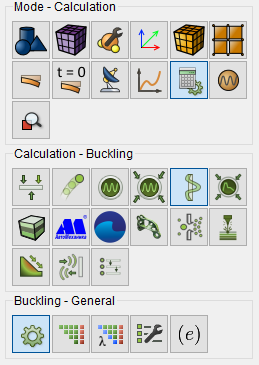
Set the following parameters:
Dimensions: 3D;
Type: Linear;
Number of buckling modes: 10.
Click Apply.
2. Set additional settings.
On the command bar, select the calculation settings module (Mode - Calculation Settings, Calculation Settings - Buckling, Buckling - Output Fields).
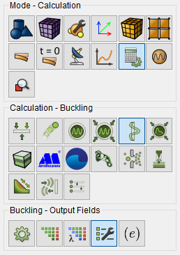
Set the following parameters:
Calculate nodal and reaction forces.
Click Apply.
Click Start Calculation.
3. In a pop-up window select a folder to save the result and enter the file name.
4. In the case of a successful calculation, the console displays the message: Calculation finished successfully at "date" "time".
1. Open the file with the results. There are three ways to do that.
Click Ctrl+E.
From the main menu, select Calculation. Click Open Results.
Select Results on Command Panel (Mode - Results). Click Open results.

The Fidesys Viewer window will appear in which you can view with the calculation results.
2. Display the Warp By Vector filter.
In the Warp By Vector filter in the Properties tab set parameters:
Vectors: Moda 1: displacement;
Scale Factor: 1;
Click Apply.
3. In the Warp by Vector filter, in the Display (UnstructuredGridRepresentation) tab, set:
Representation: Surface.
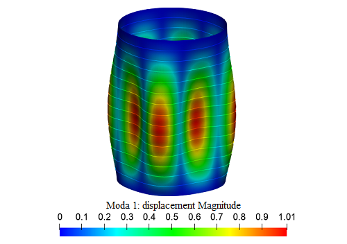
Geometry creating, meshing, setting boundary conditions and materials can be performed using the console interface. Below is a link to the program code that allows you to perform the steps described above manual, you only need to specify the full path and name.