Search the documentation
Enter at least 2 characters
Enter at least 2 characters
 |
CAE Fidesys 9.0 Documentation |
We consider an example with a beam construction. Structural damping is specified.
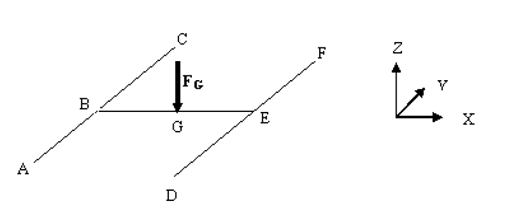
The model is rigidly fixed at points A, D, C, F. A force dependent on frequency is applied to the middle of the BE face. The sides of the structure have the same length: AB = BC = DE = EF = BG = EG = 2.5 m. Material parameters: Young's modulus E = 2e11 Pa, Poisson’s ratio ν = 0.3, density ρ = 7800 kg / m3. Structural damping 0.1 is specified.
1. Create a structure and beams (lines).
On the command bar, select the module for constructing geometry (Mode - Geometry, Entity - Curve, Action - Create).
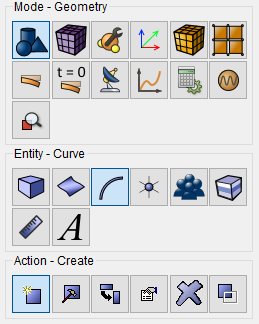
From the drop-down list, select Line. On the Build Using panel, use select Location and Direction.
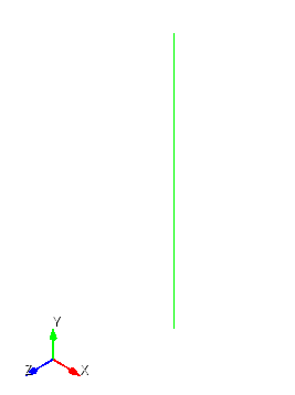
Next, enter the necessary data to create the first line:
Location: 0 0 0 (space separated);
Direction: 0 1 0;
Length: 2.5.
Click Apply.
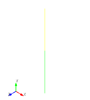
2. Specify the necessary data to create a second line:
Location: 0 2.5 0;
Direction: 0 1 0;
Length: 2.5.
Click Apply.
3. Specify the necessary data to create a third line:
Location: 0 2.5 0;
Direction: 1 0 0;
Length: 2.5.
Click Apply.
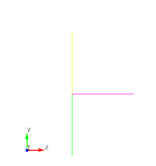
4. Specify the necessary data to create the fourth line:
Location: 2.5 2.5 0;
Direction: 1 0 0;
Length: 2.5.
Click Apply.
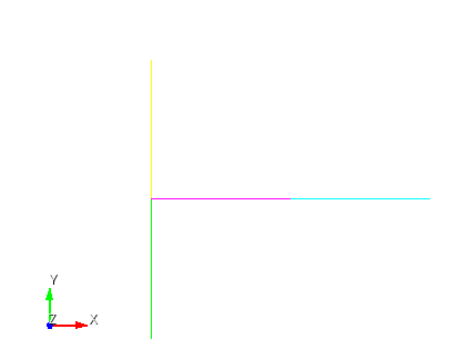
5. Specify the necessary data to create a fifth line:
Location:5 0 0;
Direction: 0 1 0;
Length: 2.5.
Click Apply.
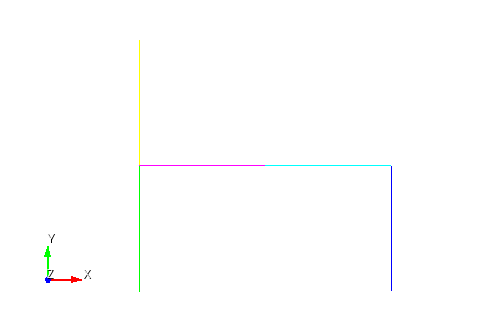
6. Specify the necessary data to create the sixth line:
Location:5 2.5 0;
Direction: 0 1 0;
Length: 2.5.
Click Apply.
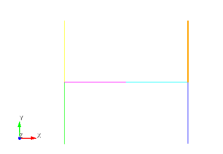
7. Splicing tops on received beams.
On the command bar, select the module for constructing geometry (Mode - Geometry, Entity - Vertex, Action - Merge).
Specify:
Vertex ID(s): all.
Click Apply.
A beam structure was created.
1. On the command bar, select the mesh module (Mode - Mesh, Entity - Curve, Action - Mesh).

Specify the following parameters:
Select Curves: all;
Settings for Curve: Equal;
Approximate Size;
Approximate Size: 0.1.
Click Apply Size.
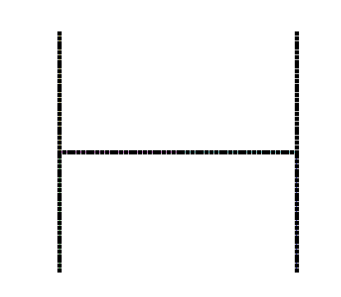
Click Mesh.
1. Create a material.
In the command bar, select the module for specifying material properties (Mode - Material, Entity -Materials Management).

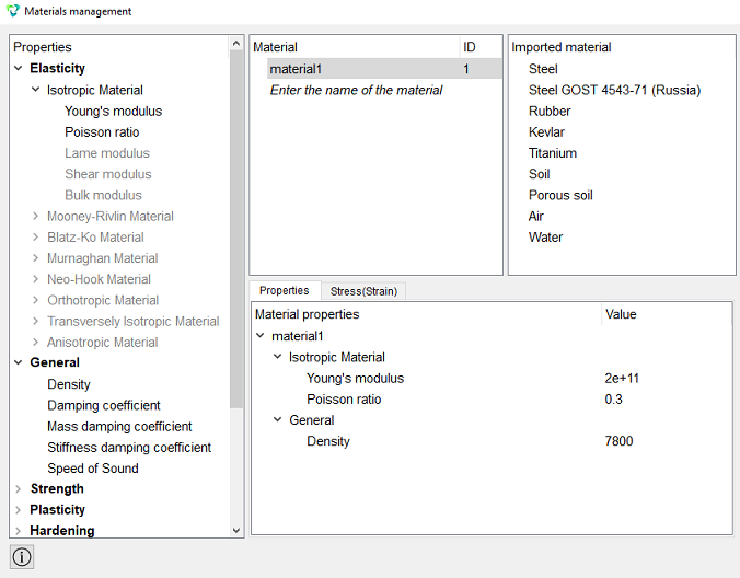
In the Materials Management window that opens, in the second column, click on the caption Enter the name of the material and write material1. Click the ENTER key.
In the left column, select Elasticity - Isotropic Material. Select with the mouse the characteristic Young's modulus. Hold down the left mouse button and drag the label to Material Properties. Double-click in the Value field next to Young's modulus and enter the number 2e11.Similarly, from the Isotropic Material section add the Poisson Ratio 0.3, Density: 7800.
Click Apply.
Close the Materials management window.
2. Create a block of the one type of material.
On the command bar, select the block management module (Mode - Blocks, Entity - Block, Action - Add).

Set the following parameters:
Block ID: 1;
Entity List: Curve;
Entity ID(s): all.
Click Apply.
3. Set the block parameters.
On the command bar, select the block management module (Mode - Blocks, Entity - Block, Action - Block properties/parameters).

Set the following parameters:
Block Name: Block 1 (ID 1);
Category: Beam;
Material: material1;
Coordinate System: Global Cartesian;
Order: 1;
Block Properties ID: Click on the button  .
.
Set the following options:
CS Rotation Angle: 0;
Offset to: Centroid;
Profile Mesh Quality: Fine;
Select profile: Ellipse;
Minor axis (b): 0.1;
Major axis (a): 0.1.
Click Apply.
Close the window Set Beam Properties.
Click Apply.
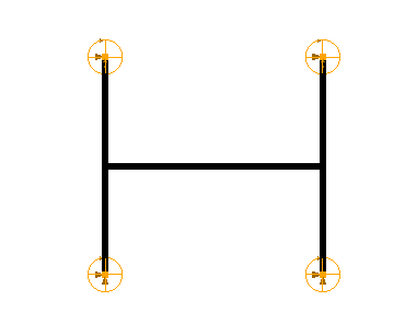
1. Fix the vertices A, D, C, F through all displacements and rotations.
On the command panel, select the boundary conditions module (Mode - Boundary Conditions, Entity - Displacement, Action - Create).

Set the following parameters:
Entity List: Vertex;
Entity ID(s): 1 4 9 12 (or select the vertices with the mouse by pressing the Ctrl key);
Degrees of Freedom: All;
DOF Value: 0 (can not fill).
Click Apply.
2. Apply a force dependent on frequency.
On the command panel, select the boundary conditions module (Mode - Boundary Conditions, Entity - Force, Action - Create).
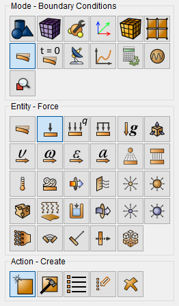
Set the following parameters:
Force Entity List: Vertex;
Entity ID(s): 6 (or select a vertex with the mouse, as shown in the figure);
Force: 1;
Direction: 0 0 -1 (negative direction along the z axis).
Click Apply.
3. Set the frequency dependence.
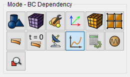
On the command panel, select the module for specifying Dependency BC (Mode - BC Dependency).
In the BC Dependency window that appears, select the boundary condition Force 1 in the left column, in the Formula panel from the drop-down list, select Harmonic.
Enter the following data:
Amplitude: 1e5;
Frequency: w;
Phase: 0.
Click Apply.
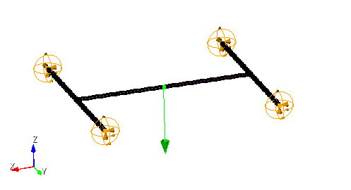
1. Set the type of problem you want to solve.
On the command bar, select the calculation settings module (Mode - Calculation Settings, Calculation Settings - Frequency Analysis, Frequency Analysis - General).
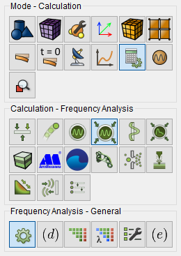
Set the following calculation parameters:
Dimension: 3D;
Number of Eigenmodes: 10;
Lowest.
Frequency Spacing Type: Uniform With Eigen Values;
Frequency Interval: 0.0 - 40.0;
Frequency Step: 0.5.
Click Apply.
2. Specify structural damping.
On the command bar, select the calculation settings module (Mode - Calculation Settings, Calculation Settings - Frequency analysis, Frequency analysis - Damping).
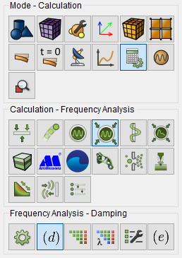
Set the following calculation parameters:
Structural damping: 0.1.
Click Apply.
Click Start Calculation.
3. In the window that appears, select the directory in which the result will be stored, and enter the file name.
4. In the case of a successful calculation, the console displays the message: Calculation finished successfully at "date" "time".
1. Compare the results displayed on the command line with the results below:
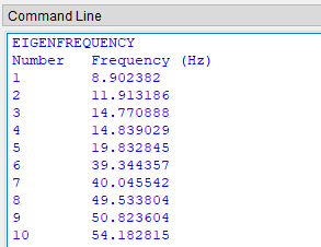
2. Open the file with the results. There are three ways to do that.
Click Ctrl+E.
From the main menu, select Calculation. Click Open Results.
Select Results on Command Panel (Mode - Results). Click Open results.

The FidesysViewer window will appear, in which you can view the results of the calculation.
3. Select a point on the surface with the Select Points  .
.
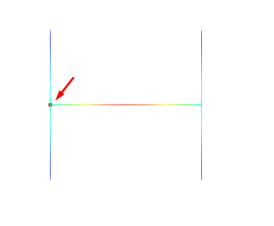
In the standard line, select Filters -> Alphabetical -> Harmonic Analysis.
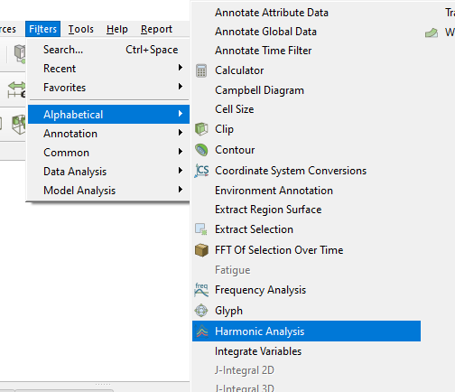
For the Harmonic Analysis in the Tree, in the Properties tab Click Apply
In the section Row Parameters for the X-axis that appears, select only the Displacement (Amplitude)_ Z.
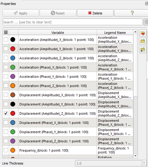
On the right side of the screen received the desired graph.
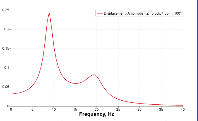
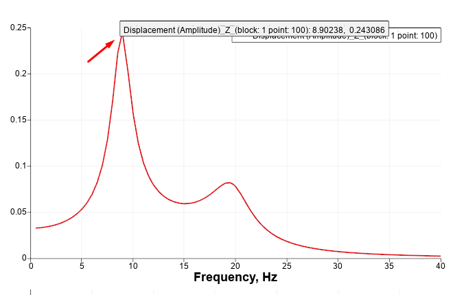
Hover over one of the peaks, then the pop-up text will display the amplitude value corresponding to the frequency.
Geometry creating, meshing, setting boundary conditions and materials can be performed using the console interface. Below is a link to the program code that allows you to perform the steps described above manual, you only need to specify the full path and name.