Search the documentation
Enter at least 2 characters
Enter at least 2 characters
 |
CAE Fidesys 9.0 Documentation |
In this example, the stress-strain state of a plate with hole, consisting of three layers of different materials. Attached to the top constant pressure over 12 steps, pressure acts on the edge of the hole, specified in the table.
1. Create a rectangle.
On the command bar, select the module for constructing surface geometry (Mode - Geometry, Entity - Surface, Action - Create).

From the list of geometric primitives, select Rectangle.
Set the following parameters:
Width: 243;
Height: 546;
ZPlane.
Click Apply.

2. Move the created rectangle.
On the command bar, select the module for constructing surface geometry (Mode - Geometry, Entity - Surface, Action - Transform).
From the list of possible transformations, select Move.
Set the following parameters:
Surface ID(s): 1;
Including Merged: uncheck;
Select Method: Distance;
X Distance: 121.5.
Click Apply.
3. Create a circle with a radius of 70.
On the command bar, select the module for constructing surface geometry (Mode - Geometry, Entity - Surface, Action - Create).
From the list of geometric primitives, select Circle.
Set the following parameters:
Specify Circle Using: Radius;
Radius: 70;
ZPlane.
Click Apply.
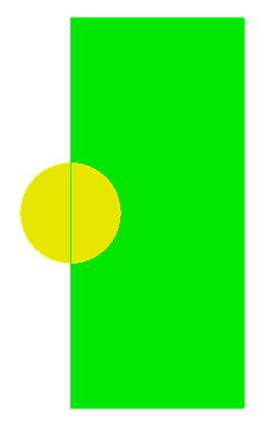
4. Subtract the circle from the rectangle.
On the command bar, select the module for constructing surface geometry (Mode - Geometry, Entity - Surface, Action - Boolean).
From the list of geometric primitives select Subtract.
Set the following parameters:
A Surface ID(s): 1;
B Surface ID(s): 2.
Click Apply.

5. Cut the surface into several pieces.
On the command bar, select the module for constructing surface geometry (Mode - Geometry, Entity - Surface, Action - Webcat).
From the list of geometric primitives select Coordinate Plane.
Set the following parameters:
Body ID(s): 1;
Plane: ZX;
Offset Value: 90.
Click Apply.
Set the following parameters:
Body ID(s): 1;
Plane: ZX;
Offset Value: -80.
Click Apply.
6. Splice surfaces.
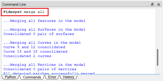
Type the following command into the command line:
1. Build a finite element mesh.
On the command bar, select the surface mesh module (Mode - Mesh, Entity - Surface, Action - Intervals).
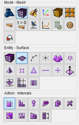
From the list of actions, select Approximate Size.
Set the following parameters:
Select Surfaces: all;
Approximate Size: 10.
Click Apply Size.
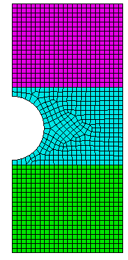
Click Mesh.
1. Specify the material.
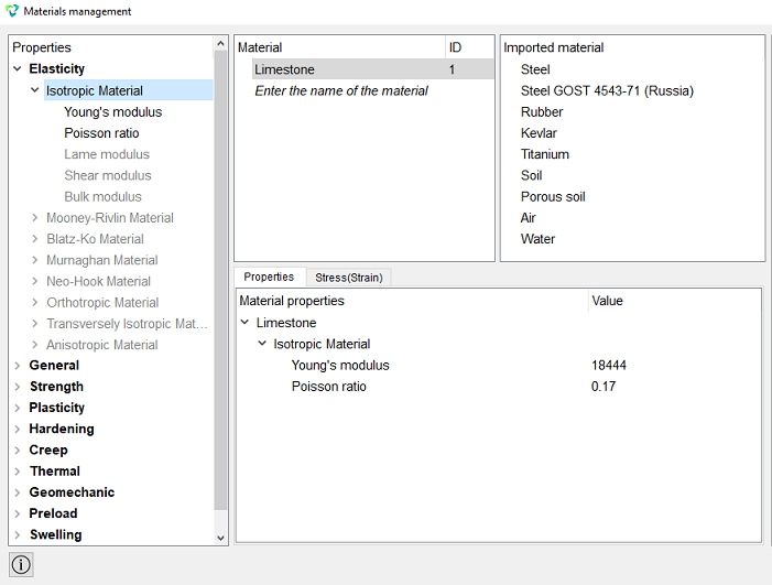
In the command bar, select the module for specifying material properties (Mode — Material, Entity — Materials Management).

1. Material Limestone:
Young's modulus: 18444;
Poisson ratio: 0.17.
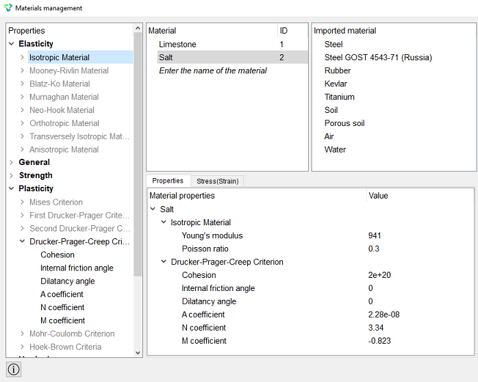
2. Material Salt:
Young's modulus: 941;
Poisson ratio: 0.3,
Cohesion: 2e+20;
Internal friction angle: 0;
Dilatacy angle: 0;
A coefficient: 2.28e-08;
N coefficient: 3.34;
M coefficient: -0.823.
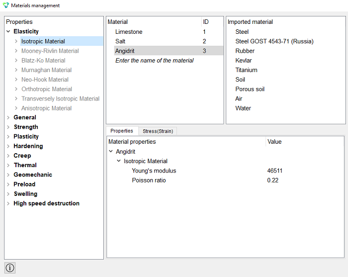
3. Material Angidrit:
Young's modulus: 46511;
Poisson ratio: 0.22.
Click Apply.
Close the Materials management window.
1. Create 1 block.
On the command bar, select the block management module (Mode — Blocks, Entity — Block, Action — Add).

Set the following parameters:
Block ID: 1;
Entity List: Surface;
Entity ID(s): 5.
Click Apply.
2. Create 2 block.
Set the following parameters:
Block ID: 2;
Entity List: Surface;
Entity ID(s): 6.
Click Apply.
3. Create 3 block.
Set the following parameters:
Block ID: 3;
Entity List: Surface;
Entity ID(s): 7.
Click Apply.
4. Set parameters for block №1.
On the command bar, select the block management module (Mode - Blocks, Entity - Block, Action - Block properties/parameters).

Set the following parameters:
Block ID(s): 1;
Category: Plane;
Material: Limestone;
Coordinate System: Global Cartesian;
Order: 1.
Click Apply.
5. Set parameters for block №2.
Set the following parameters:
Block ID(s): 2;
Category: Plane;
Material: Angidrit;
Coordinate System: Global Cartesian;
Order: 1.
Click Apply.
6. Set parameters for block №3.
Set the following parameters:
Block ID(s): 3;
Category: Plane;
Material: Salt;
Coordinate System: Global Cartesian;
Order: 1.
Click Apply.
1. Fix the left and right sides in X.
On the command panel, select the boundary conditions module (Mode - Boundary Conditions, Entity - Displacement, Action - Create).

Set the following parameters:
Entity List: Curve;
Entity ID(s): 10 13 14 16 17 19 20;
Degrees of Freedom: X.
Click Apply.
2. Fix the bottom side in Y.
Set the following parameters:
Entity List: Curve;
Entity ID(s): 3;
Degrees of Freedom: Y.
Click Apply.
3. Apply pressure to curve 1.
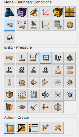
On the command panel, select the boundary conditions module (Mode - Boundary Conditions, Entity - Pressure, Action - Create).
Set the following parameters:
Entity List: Curve;
Entity ID(s): 1;
Value: 15.042.
Click Apply.
4. Apply pressure to curve 6.
Set the following parameters:
Entity List: Curve;
Entity ID(s): 6;
Value: 1.
Click Apply.
5. Set up a tabular relationship for pressure.
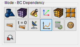
On the command panel, select the module for specifying Dependency BC (Mode - BC Dependency).
In the BC Dependency window, select Pressure 2, go to the Table tab and fill in lines like this:
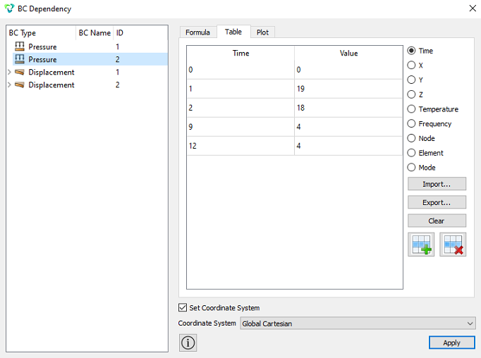
Click Apply.
1. Set the type of problem you want to solve.
On the command bar, select the calculation settings module (Mode - Calculation Settings, Calculation Settings - Static, Static - General).

Set the following parameters:
Dimensions: 2D;
Plain State: Plane Strain;
Model: Elasticity, Plasticity;
Set Static Load Steps Count;
Load Steps Count: 12;
Set Nonlinear Solver Options:
- Start Load Substeps: 10;
- Min Load Substeps: 10;
- Max Load Substeps: 100000;
- Max Iterations: 50;
- Tolerance: 1e-3;
- Target Iterations: 5;
- Remove checkbox Line Search.
Click Apply.
Click Start Calculation.
2. In the window that appears, select the directory in which the result will be saved, and enter the file name.
3. In the case of a successful calculation, the console displays the message: Calculation finished successfully at "date" "time".
1. Open the file with the results. There are three ways to do that.
Click Ctrl+E.
From the main menu, select Calculation. Click Open Results.
Select Results on Command Panel (Mode - Results). Click Open results.

The FidesysViewer window will appear, in which you can view the calculation results.
2. Display creep deformations for the model.
In the FidesysViewer window, on the toolbar, set the following options:
Display field: Creep Strain;
Display Component: XX-ZZ.

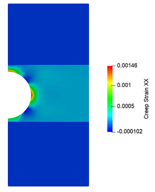
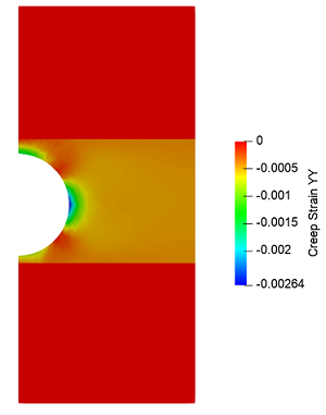
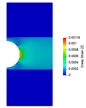
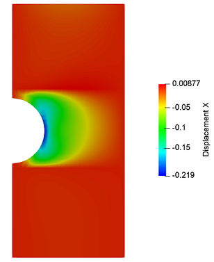
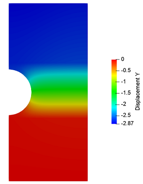
3. Display the Displacement on the model. Set the following options:

Geometry creating, meshing, setting boundary conditions and materials can be performed using the console interface. Below is a link to the program code that allows you to perform the steps described above manual, you only need to specify the full path and name.