Search the documentation
Enter at least 2 characters
Enter at least 2 characters
 |
CAE Fidesys 9.0 Documentation |
The problem of loading by internal pressure of a cylinder with a power shell consisting of a double spiral layer and an annular winding on a cylindrical part is considered.
1. Create a sphere.
On the command bar, select the module for constructing volume geometry (Mode — Geometry, Entity — Volume, Action — Create).

From the list of geometric primitives, select Sphere.
Set the following parameters:
Radius: 1.
Click Apply.
2. Create a second sphere.
On the command bar, select the module for constructing volume geometry (Mode — Geometry, Entity — Volume, Action — Create).
From the list of geometric primitives, select Sphere.
Set the following parameters:
Radius: 1.
Click Apply.
3. Move the second sphere.
On the command bar, select the module for constructing volume geometry (Mode — Geometry, Entity — Volume, Action — Transform).
From the list of geometric primitives, select Move.
Set the following parameters:
Volume ID(s): 2;
Select Method: Distance;
X Distance: 5.
Click Apply.
4. Create a circular cylinder.
On the command bar, select the module for constructing volume geometry (Mode — Geometry, Entity — Volume, Action — Create).
From the list of geometric primitives, select Cylinder.
Set the following parameters:
Height: 5;
Circular;
Radius: 1.
Click Apply.
5. Rotate the cylinder.
On the command bar, select the module for constructing volume geometry (Mode — Geometry, Entity — Volume, Action — Transform).
From the list of geometric primitives, select Rotate.
Set the following parameters:
Volume ID(s): 3;
Angle: 90;
Rotate About: Y-Axis.
Click Apply.
6. Move the cylinder.
On the command bar, select the module for constructing volume geometry (Mode — Geometry, Entity — Volume, Action — Transform).
From the list of geometric primitives, select Move.
Set the following parameters:
Volume ID(s): 3;
Select Method: Distance;
X Distance: 2.5.
Click Apply.
7. Unite the volumes.
On the command bar, select the module for constructing volume geometry (Mode — Geometry, Entity — Volume, Action — Boolean).
From the list of geometric primitives, select Unite.
Set the following parameters:
Volume ID(s): 2 3 1.
Click Apply.
8. Copy the surface of the model.
On the command bar, select the module for constructing surface geometry (Mode — Geometry, Entity— Surface, Action — Create).

From the list of geometric primitives, select Copy and Transform.
Set the following parameters:
Surface ID(s): 3 7 6;
Transform Copied Surfaces: Move;
X, Y,Z: (0,0,0);
Repeat: 1.
Click Apply.
9. Delete the volume.
On the command bar, select the module for constructing volume geometry (Mode — Geometry, Entity — Volume, Action — Delete).
Set the following parameters:
Volume ID(s): 2.
Click Apply.
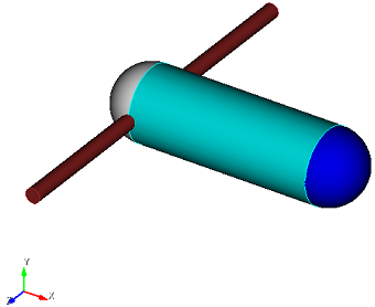
10. Create a circular cylinder.
On the command bar, select the module for constructing volume geometry (Mode — Geometry, Entity— Volume, Action — Create).
From the list of geometric primitives, select Cylinder.
Set the following parameters:
Height: 10;
Circular;
Radius: 0.2.
Click Apply.
11. Rotate the cylinder.
On the command bar, select the module for constructing volume geometry (Mode — Geometry, Entity — Volume, Action — Transform).
From the list of geometric primitives, select Rotate.
Set the following parameters:
Volume ID(s): 7;
Angle: 90;
Rotate About: Y-Axis.
Click Apply.
12. Move the cylinder.
On the command bar, select the module for constructing volume geometry (Mode — Geometry, Entity — Volume, Action — Transform).
From the list of geometric primitives, select Move.
Set the following parameters:
Volume ID(s): 7;
Select Method: Distance;
X Distance: 2.
Click Apply.
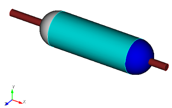
13. Cut the new cylinder relative to the initial geometry.
On the command bar, select the module for constructing surface geometry (Mode — Geometry, Entity — Surface, Action — Webcut).
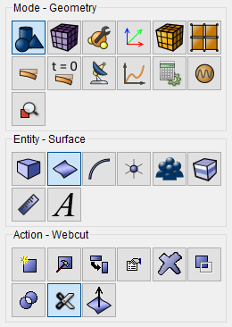
From the list of geometric primitives, select Sheet Extended From Surface.
Set the following parameters:
Body ID(s): 6;
With Surface ID(s): 11.
Click Apply.
14. Do the same for the body 5.
Set the following parameters:
Body ID(s): 5;
With Surface ID(s): 11.
Click Apply.
15. Delete the volume.
On the command bar, select the module for constructing volume geometry (Mode — Geometry, Entity — Volume, Action — Delete).
Set the following parameters:
Volume ID(s): 7.
Click Apply.
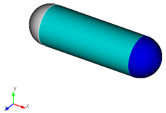
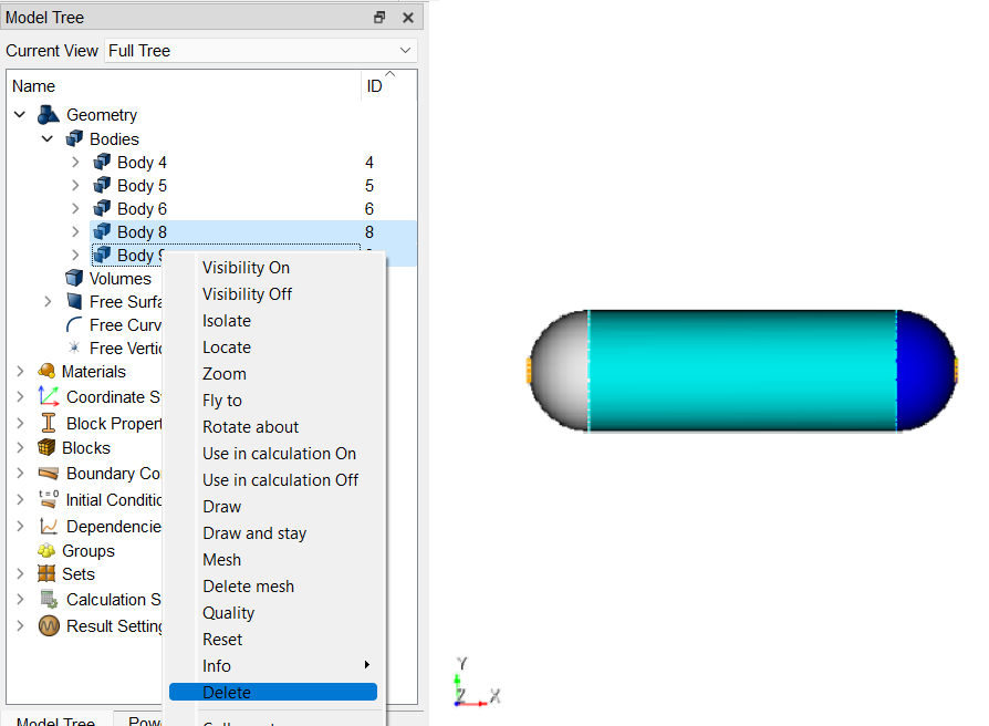
16. Delete bodies 8 and 9. To do this, hold down the Ctrl key and select in the object tree of these bodies and in the context menu, click Delete.
17. Merge all the curves.
On the command bar, select the module for constructing geometry (Mode — Geometry, Entity— Curve, Action — Merge).
From the drop-down list, select Merge.
Set the following parameters:
Curve ID(s): all.
Click Apply.
1. On the command bar, select the surface mesh module (Mode - Mesh, Entity- Surface, Action - Intervals).
From the pop-up list, select Approximate Size.
Set the following parameters:
Select Surfaces: 8 16 14;
Approximate Size: 0.04.
Click Apply Size.
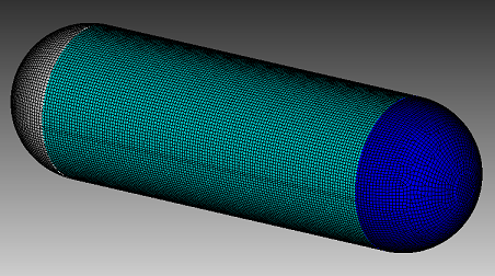
2. On the command bar, select the surface mesh module (Mode - Mesh, Entity - Surface, Action - Mesh).
From the pop-up list, select QuadDominant.
Set the following parameters:
Select Surfaces: 8.
Click Apply Scheme.
Click Mesh.
1. Create the material.
In the command bar, select the module for specifying material properties (Mode — Material, Entity — Materials Management).

In the window that opens Materials Management drag from the third columns material Kevlar.
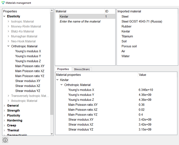
Click Apply.
Close the Materials management window.
2. Create a block of the same type of material.
On the command bar, select the block management module (Mode — Blocks, Entity— Block, Action — Add).

Set the following parameters:
Block ID: 1;
Entity List: Surface;
Entity ID(s): 14 16.
Click Apply.
3. Create a second block.
On the command bar, select the block management module (Mode — Blocks, Entity— Block, Action — Add ).
Set the following parameters:
Block ID: 2;
Entity List: Surface;
Entity ID(s): 8.
Click Apply.
4. Set the parameters for the first block.
On the command bar, select the block management module (Mode — Blocks, Entity — Block, Action — Block properties/parameters).

Set the following parameters:
Block ID(s): 1;
Category: Shell;
Order: 2.
Set the shell properties, to do this, click on the button  .
.
Set the following options:
Thickness: 0.005;
Material: Kevlar;
Angle: 30.
Click  Add Row and set the parameters:
Thickness: 0.005;
Material: Kevlar;
Angle: -30.
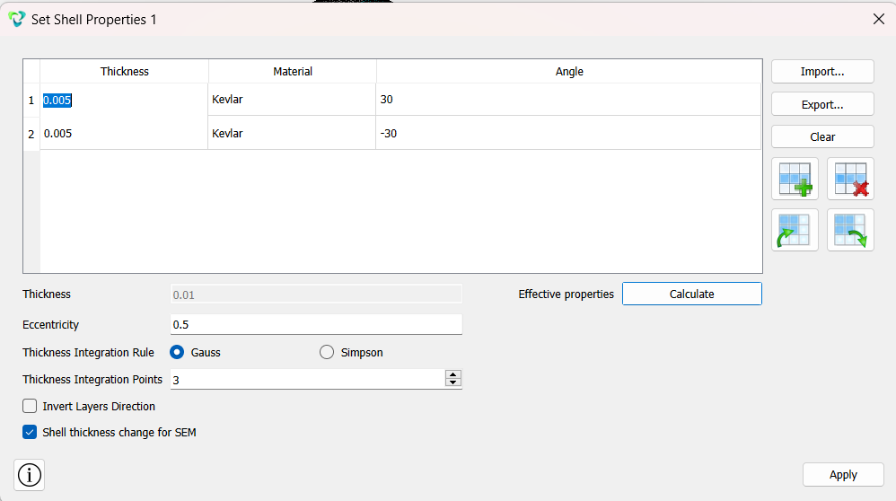
Click Apply. Close the window Set Shell property.
Click Apply.
5. Set the parameters for the second block.
On the command bar, select the block management module (Mode — Blocks, Entity — Block, Action — Block properties/parameters).
Set the following parameters:
Block ID(s): 2;
Category: Shell;
Order: 2.
Set the shell properties, to do this, click on the button .
Set the following options:
Thickness: 0.005;
Material: Kevlar;
Angle: 30.
Click Add Row and set the parameters:
Thickness: 0.005;
Material: Kevlar;
Angle: -30.
Click Add Row and set the parameters:
Thickness: 0.005;
Material: Kevlar;
Angle: 90.
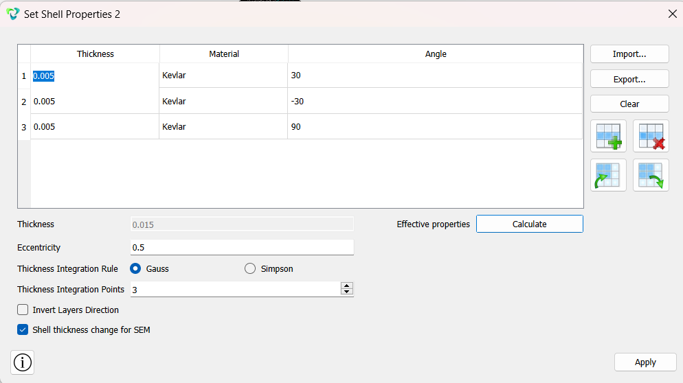
Click Apply.
Close the window Set Shell Properties.
Click Apply.
1. Fix one curve of the hole for all movements.
On the command panel, select the boundary conditions module (Mode — Boundary Conditions, Entity — Displacement, Action — Create).

Set the following parameters:
Entity List: Curve;
Entity ID(s): 10;
Degrees of Freedom: X, Y, Z.
Click Apply.
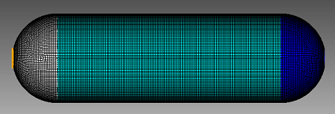
2. Fix the other hole curve by Y and Z.
On the command panel, select the boundary conditions module (Mode — Boundary Conditions, Entity — Displacement, Action — Create).
Set the following parameters:
Entity List: Curve;
Entity ID(s): 12;
Degrees of Freedom: Y, Z.
Click Apply.
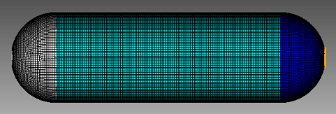
3. Apply pressure to all surfaces.
On the command panel, select the boundary conditions module (Mode — Boundary Conditions, Entity — Pressure, Action — Create).
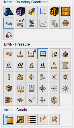
Set the following parameters:
Entity List: Surface;
Entity ID(s): all;
Value: -5e6.
Click Apply.
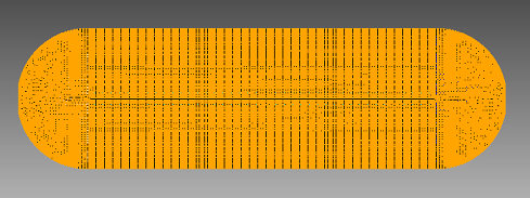
1. Specify the type of task you want to solve.
On the command bar, select the calculation settings module (Mode — Calculation Settings, Calculation Settings — Static, Static — General).

Set the following calculation parameters:
Dimension: 3D;
Model: Elasticity.
Click Apply.
2. Set additional settings.
On the command bar, select the calculation settings module (Mode — Calculation Settings, Calculation Settings — Static, Static — Output Fields).
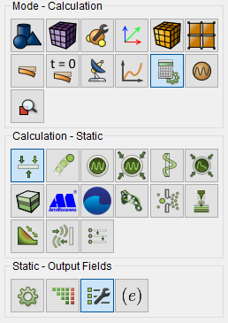
Check the following options:
Results in 3D View (for Beams and Shells).
Click Apply.
Click Start Calculation.
3. In the window that appears, select the directory where the result will be saved and enter the file name.
4. In the case of a successful calculation, the console displays the message: Calculation finished successfully at "date" "time".
1. Open the file with the results. There are three ways to do that.
Click Ctrl+E.
From the main menu, select Calculation. Click Open Results.
Select Results on Command Panel (Mode - Results). Click Open results.

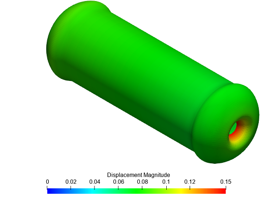
2. Display the Warp by Vector filter.
On the command bar, select Filters - Alphabetical - Warp By Vector.
Configure the filter properties:
Vectors: Displacement;
Scale Factor: 6.2762;
View: Surface.
Click Apply.
3. Show the Threshold filter for all layers.
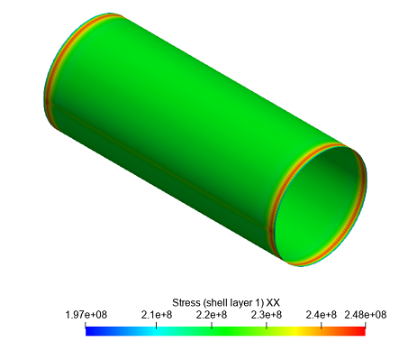
On the command bar, select Filters — Alphabetical — Threshold.
Specify the settings in the filter properties:
Input Array: Block ID;
Minimum: 2;
Maximum: 2.
Click Apply.
From the first drop-down list, select Stress (shell layer 1), from the second, XX.
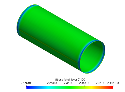
From the first drop-down list, select Stress (shell layer 2), from the second, XX.
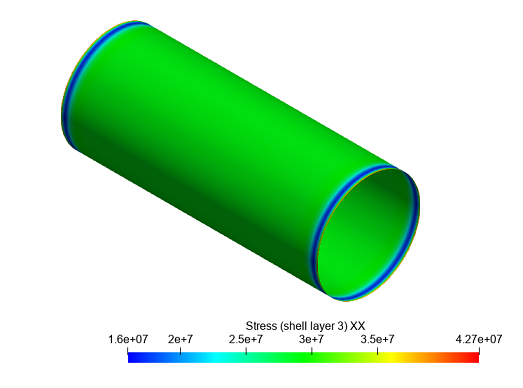
From the first drop-down list, select Stress (shell layer 3), from the second, XX.
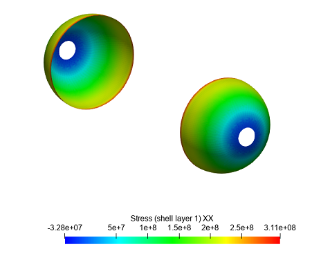
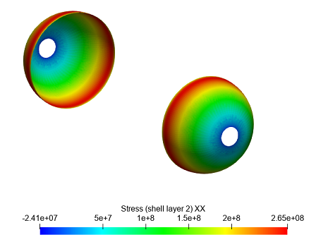
4. Display the voltages for the tank bottoms.
Set the settings in the filter properties:
Input Array: Block ID;
Minimum: 1;
Maximum: 1.
Click Apply.
From the first drop-down list, select Stress (shell layer 1), from the second, XX.
From the first drop-down list, select Stress (shell layer 2), from the second, XX.
Geometry construction, grid generation, boundary conditions and materials can be performed using the console interface. Below is a link to the program code that allows you to perform the steps described above in the manual, you only need to specify the full path and the name of the saved file yourself.