Search the documentation
Enter at least 2 characters
Enter at least 2 characters
 |
CAE Fidesys 9.0 Documentation |
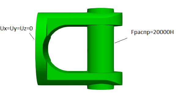
We consider a simplified model of a fork with a pin. Tensile force F=20000 Н distributed over a surface is applied to the central part of the pin.
1. Import geometry.
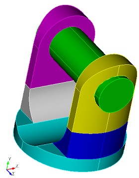
In the top line, select Menu - File - Import. Specify the path to the file shtift.stp. If you cannot download the model, right-click on its name and select Save target as.... Then specify the folder where you want to go. place it.
The file can also be found in the folder C:\Program Files\Fidesys\CAE-Fidesys-9.0\preprocessor\bin\help\fidesys_example_tutorials\TestsFromHelp\models and select the specified model.
In the window that appears, click Finish, leaving all the default options.
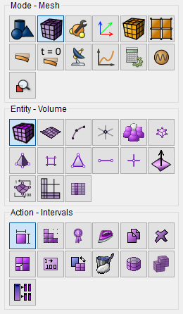
1. On the command bar, select the mesh module (Mode - Mesh, Entity - Volume, Action - Intervals).
Set:
In the drop-down list select: Automatic Sizing;
Select Volumes: All.
Click Apply Size.
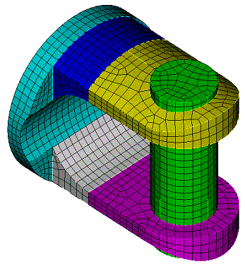
Click Mesh.
1. Create the material.
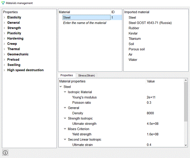
In the command bar, select the module for specifying material properties (Mode - Material, Entity — Materials Management).

In the Manage materials window that opens, from the third column to the second, transfer the material "Steel".
Click Apply.
Close the Materials management window.
2. Create a block of one material type.
On the command bar, select the block management module (Mode - Blocks, Entity - Block, Action - Add).

Set the following parameters:
Block ID: 1;
Entity List: Volume;
Entity ID(s): all.
Click Apply.
3. Set the block parameters.
On the command bar, select the block management module (Mode - Blocks, Entity - Block, Action - Block properties/parameters).

Set the following parameters:
Block ID(s): 1 or all;
Category: Solid;
Material: Steel;
Coordinate System: Global Cartesian;
Order: 2.
Click Apply.
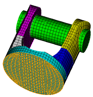
1. Fix the sides of the part from the symmetry condition.
On the command panel, select the boundary conditions module (Mode - Boundary Conditions, Entity — Displacement, Action - Create).

Set the following parameters:
Entity List: Surface;
Entity ID(s): 48;
Degrees Of Freedom: All;
DOF Value: 0 (you can leave it blank).
Click Apply.
2. Specify the force distributed over the surface F = 20000 Н.
On the command panel, select the boundary conditions module (Mode - Boundary Conditions, Entity – Distributed force, Action - Create).
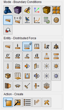
Set the following parameters:
Entity List: Surface;
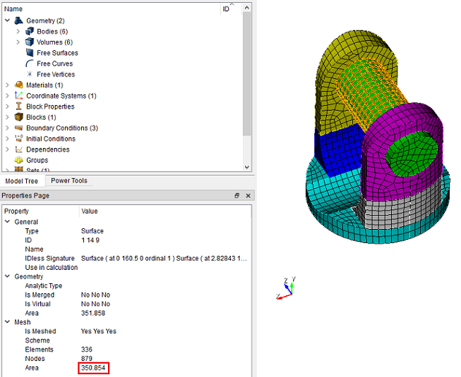
Entity ID(s): 14 1 9;
Force: 20000;
Direction Vector: (0 1 0) (positive axis y direction).
Click Apply.
Expression in brackets {} means the use of the embedded language Aprepro. To set the force distributed over the surface in the CAE Fidesys package, the force value must be divided by the surface area. The surface area can be found in the Tree on the left. To do this, select three surfaces with the mouse in the Tree or on the model. Their area will appear on the Properties page 350.854.
3. Setting the contact condition.
On the command panel, select the boundary conditions module (Mode - Boundary Conditions, Entity — Contact, Action - Create).
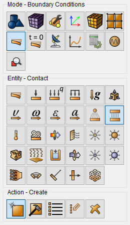
Set the following parameters:
Auto selection;
Entity List: Global;
Type: Tied;
Tolerance: 0.0005;
Method: Auto.
Click Apply.
1. Set the type of problem you want to solve.
On the command bar, select the calculation settings module (Mode - Calculation Settings, Calculation Settings - Static, Static - General).

Set the following calculation parameters:
Dimensions: 3D;
Model: Elasticity.
Click Apply.
Click Start Calculation.
2. Specify Force Calculation.
On the command bar, select the calculation settings module (Mode - Calculation Settings, Calculation Settings - Static, Static - Output Fields).
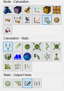
Set the flag Calculate nodal and reaction forces.
Click Apply.
Click Start Calculation.
Important: Without the Calculate nodal forces and forces enabled reactions this field is not calculated.
3. In the window that appears, select the directory where the result will be saved and enter the file name.
4. In the case of a successful calculation, the console displays the message: Calculation finished successfully at "date" "time".
1. Open the file with the results. There are three ways to do it:
Click Ctrl+E.
Select Calculation - Open Results in the Main Menu. Click Open last result.
Select Results on Command Panel (Mode — Results). Click Open Results.

The FidesysViewer window will appear, in which you can view the calculation results.
Display the displacements for the deformed view of the model.

On the Properties page, specify the Scale Multiplier - 5e7.
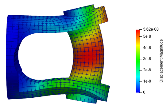
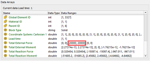
Go to the Information tab for the entire model. Find the Total External Force Field. The values in these fields for the second component should be 20000.
Geometry creating, meshing, setting boundary conditions and materials can be performed using the console interface. Below is a link to the program code that allows you to perform the steps described above manual, you only need to specify the full path and name.