Search the documentation
Enter at least 2 characters
Enter at least 2 characters
 |
CAE Fidesys 9.0 Documentation |
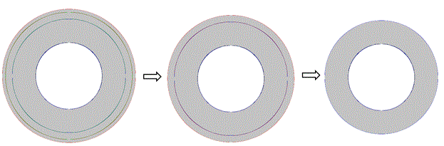
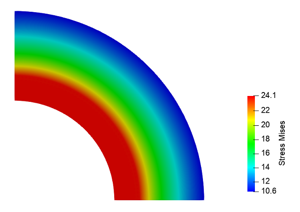
The model is a cylindrical tube consisting of three layers. Material parameters for all three layers: E = 2.1e4 N / mm2, n = 0.3, yield strength c = 24 N / m2. A uniform pressure of 14 N / mm2 is applied to the inner surface of the pipe. Fixation according with the symmetry condition. Three loading steps are specified: in the second step, the outer layer of the pipe is removed, in the third step, the next outer layer of the pipe is removed. In the process of solution, stresses are analyzed with the plastic flow and pipe thinning.
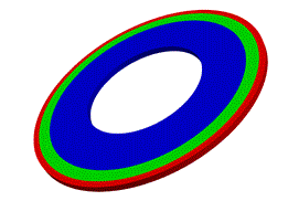
1. Create a circular surface with a radius of 100.
On the command bar, select the module for constructing surface geometry (Mode - Geometry, Entity - Surface, Action - Create).

From the list of geometric primitives, select Circle.
Set the dimensions:
Radius: 100;
Location: ZPlane.
Click Apply.
2. Create a circular surface with a radius of 170.
Set the dimensions:
Radius: 170;
Location: ZPlane.
Click Apply.
3. Create a circular surface with a radius of 190.
Set the dimensions:
Radius: 190;
Location: ZPlane.
Click Apply.
4. Create a circular surface with a radius of 200.
Set the dimensions:
Radius: 200;
Location: ZPlane.
Click Apply.
5. Subtract surface 1 from the remaining surfaces 2 3 4.
On the command bar, select the module for constructing surface geometry (Mode - Geometry, Entity - Surface, Action - Boolean).
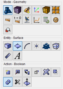
From the list of operations, select Subtract.
Set the following parameters:
Surface ID(s): 2 3 4 (surfaces from which other surface will be subtracted);
Surface ID(s): 1 (surfaces to be subtracted).
Click Apply.
6. Subtract surface 5 from surface 6.
Select volume geometry generation section on Command Panel (Mode - Geometry, Entity - Surface, Action - Boolean).
From the list of operations, select Subtract.
Set the following parameters:
Surface ID(s): 6 (surfaces from which other surface will be subtracted);
Surface ID(s): 5 (amounts to be deducted);
Check the Keep Originals box and select Keep both (A and B).
Click Apply.
7. Subtract surface 6 from surface 7.
On the command bar, select the module for constructing surface geometry (Mode - Geometry, Entity - Surface, Action - Boolean).
From the list of operations, select Subtract.
Set the following parameters:
Surface ID(s): 7 (surfaces from which other surface will be subtracted);
Surface ID(s): 6 (surfaces to be subtracted).
Click Apply.
8. Cut the body.
On the command bar, select the module for constructing surface geometry (Mode - Geometry, Entity - Surface, Action - Webcut).
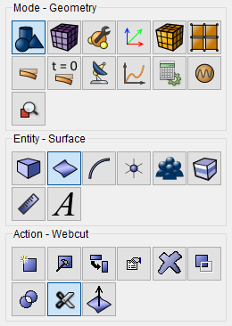
From the list of possible types of cuts, select Coordinate Plane.
Set the following parameters:
Body ID(s): all (the surfaces to be cut);
With Plane: ZX;
Offset Value: 0.
Click Apply.
9. Do the same, but in the YZ plane.
On the command bar, select the module for constructing surface geometry (Mode - Geometry, Entity - Surface, Action - Webcut).
From the list of possible types of cuts, select Coordinate Plane.
Set the following parameters:
Body ID(s): all (the surfaces to be cut);
With Plane: Plane YZ;
Offset Value: 0.
Click Apply.
10. Delete the surface.
On the command bar, select the module for constructing surface geometry (Mode - Geometry, Entity - Surface, Action - Delete).
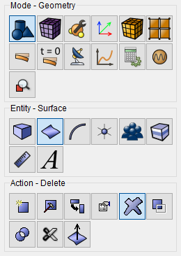
In the Surface ID field, enter the numbers - 16 20 18 17 21 19 23 25 27.
Click Apply.
11. Draw a surface to create volume.
On the command bar, select the module for constructing volume geometry (Mode - Geometry, Entity - Volume, Action - Create).

From the list of geometric primitives, select Sweep.
Set the following parameters:
Surface ID(s): all;
Perpendicular;
Distance: 10.
Set the Merge Results flag;
Set the Delete Source Surfaces flag.
Click Apply.
1. On the command bar, select the mesh module (Mode - Mesh, Entity - Curve, Action - Mesh).

Specify the degree of refining mesh:
Select Curves: 71 76 79 87 (through spaces);
Select the mesh generation method: Equal;
Select the partitioning options: Interval;
Interval: 50 (see picture).
Click Apply.
2. On the command bar, select the mesh module (Mode - Mesh, Entity - Curve, Action - Mesh).
Specify the degree of refining mesh:
Select Curves: 74 82 90 78 86 94 (through spaces);
Select the meshing method: Equal;
Select the partitioning options: Approximate Size;
Approximate Size: 2.
Click Apply.
3. On the command bar, select the mesh module (Mode - Mesh, Entity - Curve, Action - Mesh).
Specify the degree of refining mesh:
Select Curves: 75 72 80 88 77 73 81 89 (through spaces);
Select the meshing method: Evenly;
Select the partitioning options: Interval;
Interval: 1 (see picture).
Click Apply.
4. On the command bar, select the volume mesh module (Mode - Mesh, Entity - Volume, Action - Intervals).
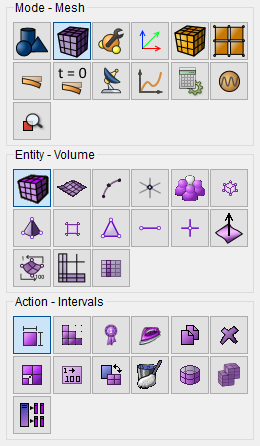
Specify the mesh spacing:
Select the meshing mode: Automatic Sizing;
Select Volumes: all.
Click Apply Size.
Click Mesh.
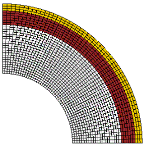
1. In the command bar, select the module for specifying material properties (Mode - Material, Entity - Materials Management).

Specify the name of the material Material 1.
2. Drag the Isotropic Material inscription from the left column, as well as, under the Mises inscription, in the Plasticity section, in the Material Properties column. Set the following parameters:
In the left window, go to Plasticity - According to Mises and drag the Yield Strength feature into the Material Properties window. Set:
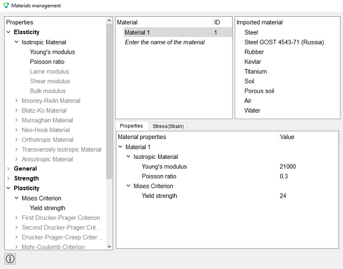
Click Apply.
Close the Materials management window.
1. On the command panel, select the boundary conditions module (Mode - Boundary Conditions, Entity - Displacement, Action - Create).

Set the following parameters:
Entity List: Surface;
Entity ID(s): 29 34 39;
Degrees of Freedom: Y.
Click Apply.
2. On the command panel, select the boundary conditions module (Mode - Boundary Conditions, Entity - Displacement, Action - Create).
Set the following parameters:
Entity List: Surface;
Entity ID(s): 31 36 41;
Degrees of Freedom: X.
Click Apply.
3. On the command panel, select the boundary conditions module (Mode - Boundary Conditions, Entity - Displacement, Action - Create).
Set the following parameters:
Entity List: Surface;
Entity ID(s): 32 37 42 18 22 26;
Degrees of Freedom: Z.
Click Apply.
4. Apply uniform pressure to the surface.
On the command panel, select the boundary conditions module (Mode - Boundary Conditions, Entity - Pressure, Action - Create).
Set the following parameters:
Entity List: Surface;
Entity ID(s): 30;
Value: 14.
Click Apply.
1. Create block of one type of material.
On the command bar, select the block management module (Mode - Blocks, Entity - Block, Action – Add).

Set the following parameters:
Block ID: 1;
Entity List: Volume;
Entity ID(s): 6.
Click Apply.
2. Create a second block.
On the command bar, select the block management module (Mode - Blocks, Entity - Block, Action – Add).
Set the following parameters:
Block ID: 2;
Entity List: Surface;
Entity ID(s): 7.
Click Apply.
3. Create the third block.
On the command bar, select the block management module (Mode - Blocks, Entity - Block, Action – Add).
Set the following parameters:
Block ID: 3;
Entity List: Surface;
Entity ID(s): 8.
Click Apply.
4. Set the block parameters.
On the command bar, select the block management module (Mode - Blocks, Entity - Block, Action - Block properties/parameters).

Set the following parameters:
Block ID(s): all;
Category: Solid;
Material: Material 1;
Coordinate System: Global Cartesian;
Order: 2.
Click Apply.
1. Set the type of problem you want to solve.
On the command bar, select the calculation settings module (Mode - Calculation Settings, Calculation Settings - Static, Static - General).

Set the following calculation parameters:
Dimensions: 3D;
Model: Elasticity, Plasticity;
Set Static Load Steps Count;
Load Steps Count: 3.
Click on  opposite the Load Steps Count, to configure
active sample times for blocks.
opposite the Load Steps Count, to configure
active sample times for blocks.
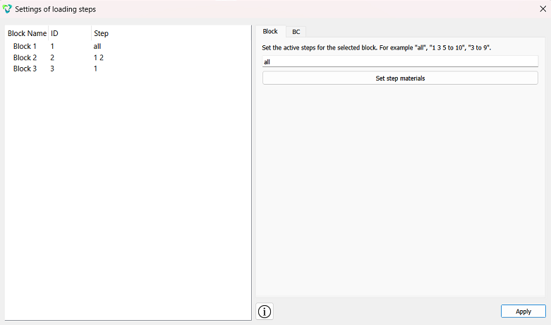
In the left column, click on Block 2. On the Blocks tab, set active calculation steps -1 2 (separated by a space). In the left column, click on inscription Block 3 and on the Blocks tab set the active calculation step to -1.
.
Click Apply. Close the window.
Click Apply.
Click Start Calculation.
2. In the window that appears, select the directory in which the result will be saved, and enter the file name.
3. In the case of a successful calculation, the console displays the message: Calculation finished successfully at "date" "time".
1. Open the file with the results. There are three ways to do that.
Click Ctrl+E.
From the main menu, select Calculation. Click Open Results.
Select Results on Command Panel (Mode - Results). Click Open results.

For postprocessor analysis, go to the FidesysViewer window.
2. In the top pane, select the reqired result data to display. From the first drop-down list, select Stress, from the second - Mises, from the third - Surface.

In the step view panel, set step 1. You should see the image in the
initial state. Next, click on Play .
You should see the sequential removal of layers on the model according to the loading history.
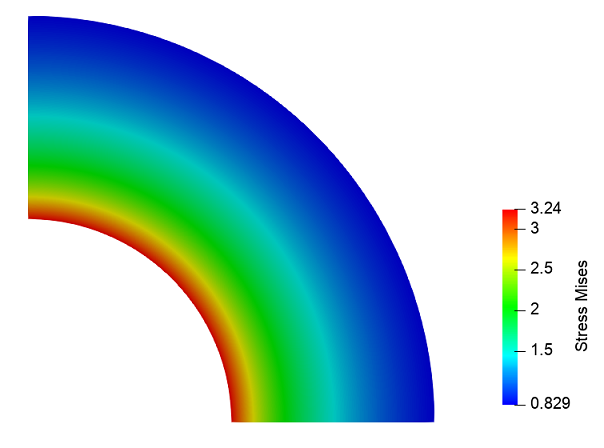
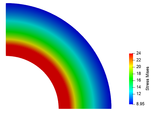

Geometry creating, meshing, setting boundary conditions and materials can be performed using the console interface. Below is a link to the program code that allows you to perform the steps described above manual, you only need to specify the full path and name.