Search the documentation
Enter at least 2 characters
Enter at least 2 characters
 |
CAE Fidesys 9.0 Documentation |
We consider the problem of a disk rotation around its axis with a constant angular velocity 1 с-1.
1. Create the first circle with radius 100.
On the command bar, select the module for constructing surface geometry (Mode — Geometry, Entity — Surface, Action — Create).

Select Circle in the list of geometric elements.
Set the following parameters:
Specify Circle Using: Radius;
Radius: 100;
Plane: ZPlane.
Click Apply.
2. Create the second circle with radius 170.
On the command bar, select the module for constructing surface geometry (Mode — Geometry, Entity — Surface, Action — Create).
Select Circle in the list of geometric elements.
Set the following parameters:
Specify Circle Using: Radius;
Radius: 170;
Plane: ZPlane.
Click Apply.
3. Subtract the first circle from the second one.
On the command bar, select the module for constructing surface geometry (Mode - Geometry, Entity - Surface, Action - Boolean).
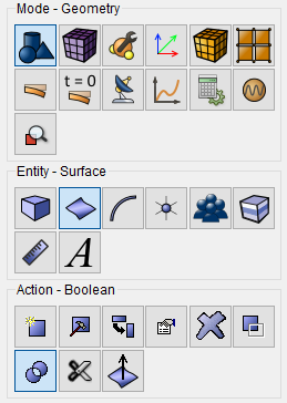
Select Subtract in the list of operations.
Set the following parameters:
A Surface ID(s): 2 (surfaces from which other surfaces will be subtracted);
B Surface ID(s): 1 (surfaces to be subtracted).
Click Apply.
4. Create volume using surface sweep.
On the command bar, select the module for constructing volume geometry (Mode — Geometry, Entity — Volume, Action — Create).

Select Sweep from the list of geometric primitives.
Surface ID(s): all;
Perpendicular;
Distance: 10.
Click Apply.
1. On the command bar, select the volume mesh module (Mode — Mesh, Entity — Volume, Action — Intervals).
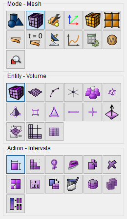
Specify the degree of mesh refinement:
Select from the dropdown list: Automatic Sizing;
Select Volumes: 2.
Click Apply Size.
Click Mesh.
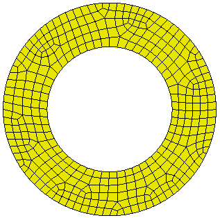
1. In the command bar, select the module for specifying material properties (Mode — Material, Entity — Materials Management).

Drag "Steel" from the "Imported Material "column to the "Material" window.
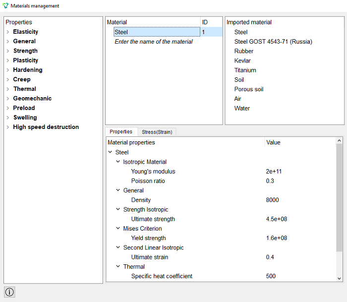
Click Apply.
Close the Material management window.
2. Create a block.
On the command bar, select the block management module (Mode — Blocks, Entity — Block, Action — Add).

Set the following parameters:
Block ID: 1;
Entity List: Volume;
Entity ID(s): 2.
Click Apply.
3. Set block parameters.
On the command bar, select the block management module (Mode — Blocks, Entity — Block, Action — Block properties/parameters).

Set the following parameters:
Block ID(s): 1;
Category: Solid;
Material: Steel;
Coordinate System: Global Cartesian;
Order: 1.
Click Apply.
1. Anchor the model along the Y axis.
On the command panel, select the boundary conditions module (Mode Boundary Conditions, Entity — Displacement, Action — Create).

Set the following parameters:
Entity List: Surface;
Entity ID(s): 5 ;
Degrees of Freedom: Z-Translation Disp, X-Rotation Disp, Y-Rotation Disp;
Click Apply.
2. Set angular velocity.
On the command panel, select the boundary conditions module (Mode — Boundary Conditions, Entity — Angular Velocity, Action — Create).
Set the following parameters:
Entity List: Volume;
Entity ID(s): 2;
Directions Z: 1.
Click Apply.
1. Set the type of the problem to be solved.
On the command bar, select the calculation settings module (Mode — Calculation Settings, Calculation Settings — Static, Static — General).

Select:
Dimension: 3D;
Model: Elasticity.
Click Apply.
Click Start Calculation.
2. In the window that appears, select the directory in which the result will be saved, and enter the file name.
3. In the case of a successful calculation, the console displays the message: Calculation finished successfully at "date" "time".
1. Open the file with the results. There are three ways to do that.
Click Ctrl+E.
From the main menu, select Calculation. Click Open Results.
Select Results on Command Panel (Mode - Results). Click Open results.

2. For postprocessor analysis go to the FidesysViewer window.
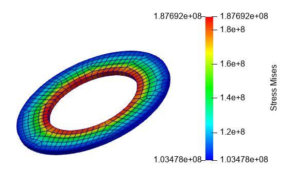
3. On the top panel, select the calculation result data to display. From the first drop-down list select Stress, from the second – Mises, from the third – Surface With Edges.

Geometry creating, meshing, setting boundary conditions and materials can be performed using the console interface. Below is a link to the program code that allows you to perform the steps described above manual, you only need to specify the full path and name.