Search the documentation
Enter at least 2 characters
Enter at least 2 characters
 |
CAE Fidesys 9.0 Documentation |
The analysis of strength characteristics under the action of loads that systematically change their magnitude or magnitude and sign differs significantly from the analysis of strength characteristics under the action of static and shock loads. Therefore, the issue of checking the strength of the material under the action of variable loads requires special attention.
In the Fidesys, starting from version 7.0, it became possible to evaluate the strength in the event of cyclic stresses using the "Fatigue" filter.
For the filter to work correctly, static or dynamic calculations must be performed.
The filter settings can be viewed in the main menu of the postprocessor in the Filters tab.
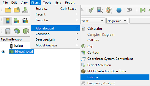
Fig. 1 - Filter "Fatigue" in the general list of postprocessor filters
The following calculation settings are implemented in the filter:
Mean Stress Correction Theory;
Cycle Type;
Fatigue Coefficient;
Cycles Count;
Stress Component;
Weller Curves Data.
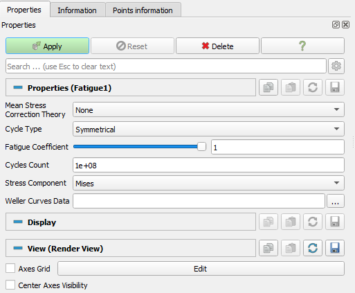
Fig. 2 - Filter Settings "Fatigue"
"Stress Component" - selection of the stress component obtained in the calculation for the analysis of fatigue characteristics.
"Cycles Count" shows how many times the structure is exposed to a given external influence.
The rest of the filter settings "Fatigue" are described below.
The magnitude of the alternating voltage of the stress cycle is calculated as half of the voltage range in the cycle. The magnitude of the destruction caused by the voltage cycle depends not only on the alternating voltage, but also on the average voltage. For example, the two cycles below have the same alternating voltage, but since they have different average voltage values, they will cause different amounts of destruction.
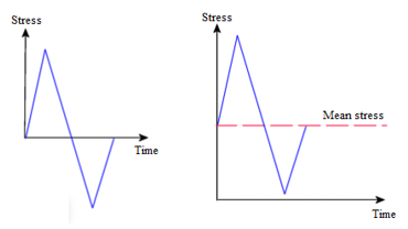
Fig. 3 - Two cycles with different average voltages
In the Fidesys software package, the average voltage can be taken into account using the theories of average voltage correction: Goodman, Gerber, Soderberg, Elliptic.
Thus, the stress amplitude, taking into account the theories of correction of average stresses, can be determined as follows:
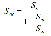
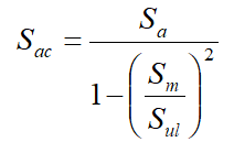
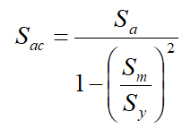
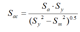
Fig. 4 - Stress amplitude taking into account the theory of correction of average stress (from left to right : Goodman, Gerber, Soderber, Elliptic)
The following designations are introduced in these formulas:
Sac - the stress amplitude, taking into account the correction;
Sa - the stress amplitude;
Sm - average voltage;
Sy - yield strength;
Sul - ultimate strength.
Fatigue tests of materials are usually carried out under strictly defined conditions. If the operating conditions of the parts differ from the conditions in which they were tested, you can apply modification coefficients to try take into account the difference. The stress amplitude are usually divided by this modification coefficient (in this case, the fatigue coefficient). Dividing the stress amplitude is equivalent to multiplying the fatigue strength limit by the fatigue coefficient. The fatigue coefficient reduces the fatigue strength and should be less than one. Please note that this coefficient applies only to the stress amplitude and does not affect the average voltage.
When calculating the fatigue strength, it is necessary to set the Weller curve for each material.
The Weller curve is the curve of the dependence of the stress amplitude on the number of cycles before the destruction of the material.
An example of the Weller curve is shown in Fig 5.
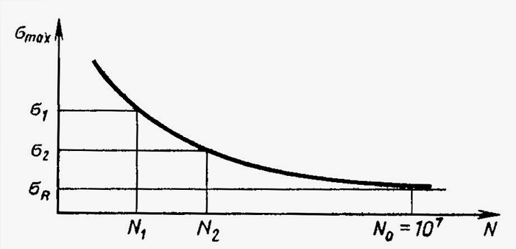
Fig. 5 - Sample of the Weller curve
On the abscissa axis - the number of cycles before the destruction of the material, on the ordinate axis - the stress amplitude.
Weller curves are imported using a single csv format table.
An example of a table of Weller curves for two materials is shown in the figure below.
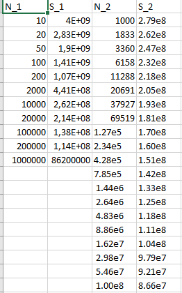
Fig. 6 - Sample of Weller curves for two materials
Thus, the Weller curves (N_1,S_1) and (N_2,S_2) refer to the materials id = 1 and id = 2 specified in the preprocessor.
In Fidesys, you can set symmetrical, zero based, and asymmetrical loading cycles.
When setting an asymmetrical cycle, you must set the asymmetry coefficient in the range from -1 to 1.
In symmetrical andzero based cycles, the asymmetry coefficient is -1 and 0.
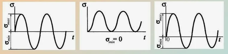
Fig. 7 - The types of cycles available in Fidesys (from left to right : Symmetrical, Zero Based, Asymmetrical)