Search the documentation
Enter at least 2 characters
Enter at least 2 characters
 |
CAE Fidesys 9.0 Documentation |
Calculation of the force occurring in the most loaded stud for a flange connection under the action of an external overturning moment. Nuts connected with flange plate and stud using rigid contact. At the same time, the hairpin not attached to the flange plate (assuming a technological gap). An independent non-conformal mesh is built on all parts.
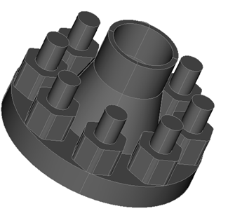
1. Download the model from the link: Download flange.stp. If you cannot download the model, right-click on its name and select Save target as.... Then specify the folder where you want to go. place it.
The file can also be found in the folder C:\Program Files\Fidesys\CAE-Fidesys-9.0\preprocessor\bin\help\fidesys_example_tutorials\TestsFromHelp\models and select the specified model.
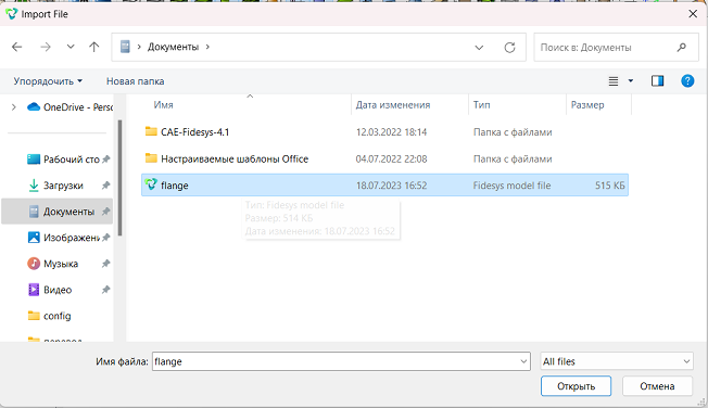
2. Import the model. On the top line, select (Menu - File - Import). Specify the path to the flange.stp file. In the window that appears, click Finish, leaving all parameters are default.
3. Increase volumes.
On the command bar, select the module for constructing volume geometry (Mode - Geometry, Entity – Volume, Action – Imprint and Merge).
From the pop-up list, select: Merge Volumes.
Set the following parameters:
Volume ID(s): 12 10 16 13 1 14 11 15.
Click Apply.
4. Merge volumes.
On the command bar, select the module for constructing volume geometry (Mode - Geometry, Entity – Volume, Action – Imprint and Merge).
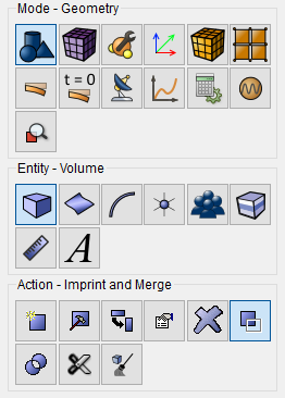
From the pop-up list, select: Merge Volumes.
Set the following parameters:
Volume ID(s): 21 30 20 31 19 32 18 25 17 26 27 24 28 23 29 22.
Click Apply.
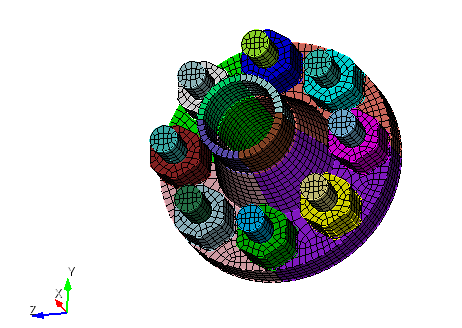
1. Create a mesh for the entire model.
On the command bar, select the volume mesh module (Mode — Mesh, Entity — Volume, Action — Intervals).
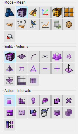
Select the mesh scheme: Automatic Sizing;
Select Volumes: all;
Move the Auto Factor slider to 5.
Click Apply Size.
Click Mesh.
1. Set the material 1.
In the command bar, select the module for specifying material properties (Mode — Material, Entity — Materials Management).

In the column "Material" enter the material name Material1.
Click Apply.
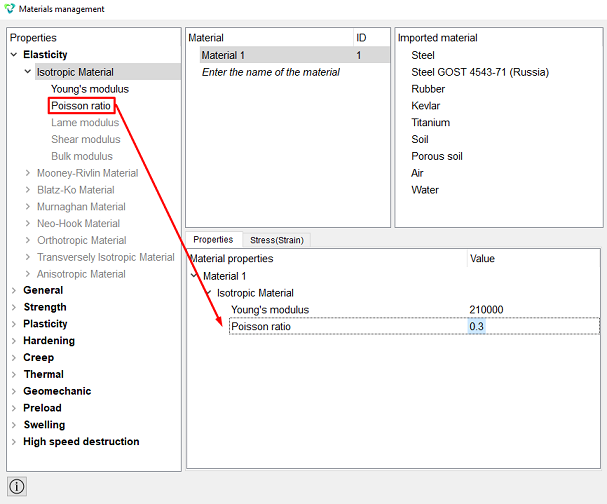
In the Material Properties column, select the created material, then drag the desired properties from the left column to it.
Drag properties and specify their value:
Young's modulus: 210000;
Poisson ratio: 0.3.
Click Apply.
Close the Materials management window.
2. Create a block for one bolt.
On the command bar, select the block management module (Mode — Blocks, Entity — Block, Action — Add).

Set the following parameters:
Block Name: Bolt;
Entity List: Volume;
Entity ID(s): 22 29.
Click Apply.
3. Create a block for the entire part.
On the command bar, select the block management module (Mode - Blocks, Entity - Block, Action - Add).
Set the following parameters:
Block Name: Detail;
Entity List: Volume;
Entity ID(s): all except 22 29.
Click Apply.
4. Set parameters for blocks.
On the command bar, select the block management module (Mode - Blocks, Entity - Block, Action - Block properties/parameters).

Set the following parameters:
Block ID(s): 1 2;
Category: Solid;
Material: Material1;
Coordinate System: Global Cartesian;
Order: 2.
Click Apply.
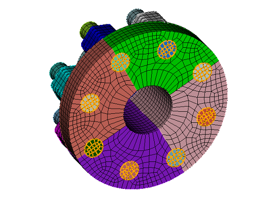
1. Secure the ends of the studs to the bottom of the flange plate along the X axis.
On the command panel, select the boundary conditions module (Mode — Boundary Conditions, Entity — Displacement, Action — Create).

Set the following parameters:
Entity List: Surface;
Entity ID(s): 259 255 251 247 275 271 267 263;
Degrees of Freedom: Х-Translation Disp;
DOF Value: 0.
Click Apply.
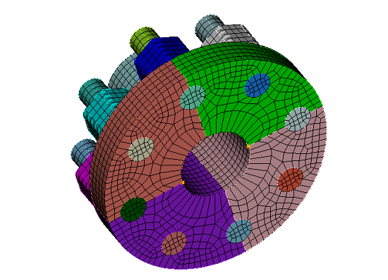
2. Make additional reinforcement of the model for all movements and rotations.
On the command panel, select the boundary conditions module (Mode — Boundary Conditions, Entity — Displacement, Action — Create).
Set the following parameters:
Entity List: Vertex;
Entity ID(s): 2 252;
Degrees of Freedom: All;
DOF Value: 0.
Click Apply.
3. Set a point force to load the model.
On the command panel, select the boundary conditions module (Mode — Boundary Conditions, Entity — Force, Action — Create).
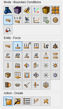
Set the following parameters:
Force Entity List: Vertex;
Entity ID(s): 333;
Force: 1e3;
Direction: 1 0 0.
Click Apply.
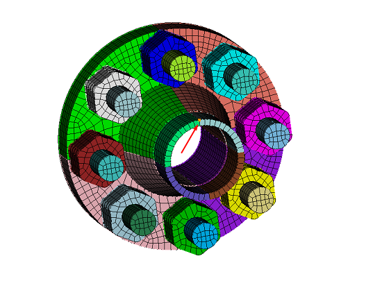
4. Set a point force to load the model.
On the command panel, select the boundary conditions module (Mode — Boundary Conditions, Entity — Force, Action — Create).
Set the following parameters:
Force Entity List: Vertex;
Entity ID(s): 349;
Force: 1e3;
Direction: -1 0 0.
Click Apply.
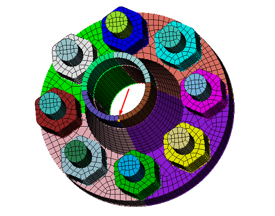
5. Set the contact condition.
On the command panel, select the boundary conditions module (Mode — Boundary Conditions, Entity — Contact, Action — Create).
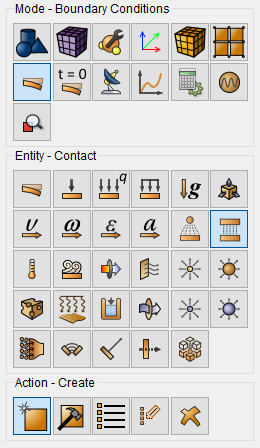
From the pop-up list, select: Auto selection.
Set the following parameters:
Entity List: Global;
Type: Tied;
Tolerance: 0.0005;
Method: Auto.
Click Apply.
6. Delete excess contact between the studs and the flange plate.
On the command panel, select the boundary conditions module (Mode — Boundary Conditions, Entity — Contact, Action — Delete).
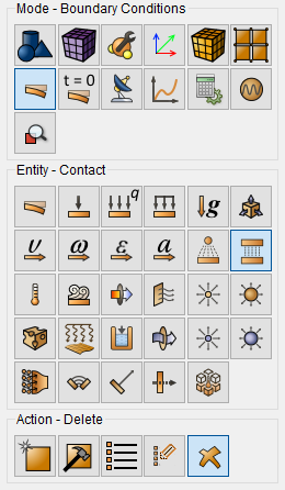
Set the following parameters:
ID: 4 to 8.
Click Apply.
7. Delete excess contact between the studs and the flange plate.
On the command panel, select the boundary conditions module (Mode — Boundary Conditions, Entity — Contact, Action — Delete).
Set the following parameters:
ID: 34 to 48.
Click Apply.
1. Specify the type of problem you want to solve.
On the command bar, select the calculation settings module (Mode — Calculation Settings, Calculation Settings — Static, Static — General).

Set the following parameters:
Dimensions: 3D;
Model: Elasticity.
Click Apply.
2. Set additional settings.
On the command bar, select the calculation settings module (Mode — Calculation Settings, Calculation Settings — Static, Static — Output Fields).
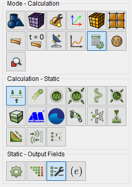
Tick the box:
Calculate nodal and reaction forces;
Output results in 3D view (for beams and shells);
Output Static or Preload intermediate results.
Click Apply.
Click Start Calculation.
3. In the window that appears, select the directory where the result will be saved and enter the file name.
4. In the case of a successful calculation, the console displays the message: Calculation finished successfully at "date" "time".
1. Open the file with the results. There are three ways to do that.
Click Ctrl+E.
From the main menu, select Calculation. Click Open Results.
Select Results on Command Panel (Mode - Results). Click Open results.

The FidesysViewer window will appear in which you can view with the calculation results.
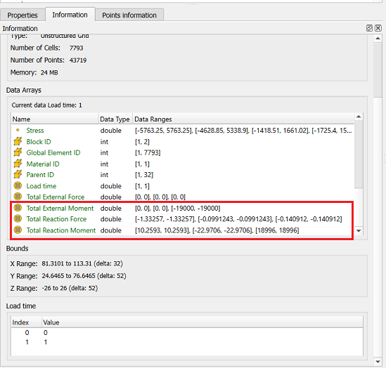
2. Check the total external moment and the total reaction moment. On panel located under the object tree, open the Information tab. Scroll the data array slider to the bottom. Find and check the range data for the total external moment and the total reaction moment.
 .
.
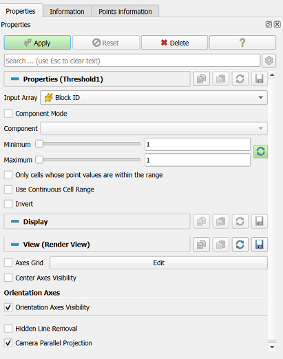
3. Check the total reaction forces for an individual bolt. IN on the top line, select (Menu - Filters - Alphabetical — Threshold).
Set the following parameters:
Input Array: Block ID;
Minimum: 1;
Maximum: 1.
Click Apply.
 .
.
From the top panel, select:
Reaction Force;
Х;
Surface With Edges.
The resulting model should show changes on only one side reaction forces.
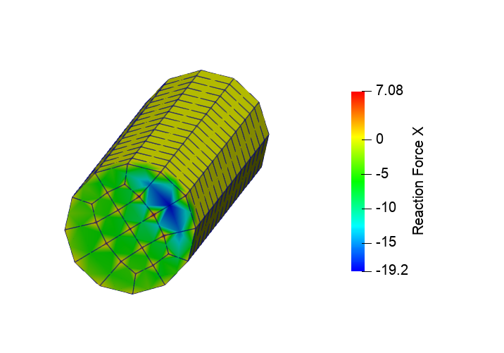 .
.
On a given surface, select all nodes manually.
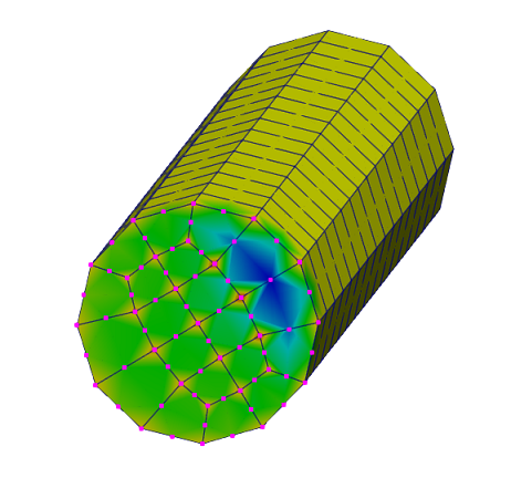 .
.
In the top line, select (Menu - Filters - Alphabetical — Extract Selection). Click Apply.
In the Information about the point, look at the Total values of Reaction Forces by X.
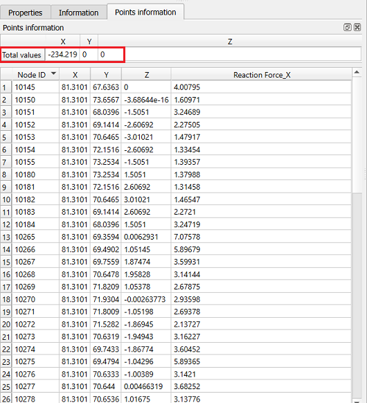 .
.
Geometry creating, meshing, setting boundary conditions and materials can be performed using the console interface. Below is a link to the program code that allows you to perform the steps described above manual, you only need to specify the full path and name.