Search the documentation
Enter at least 2 characters
Enter at least 2 characters
 |
CAE Fidesys 9.0 Documentation |
The problem of stability of a pivotally fixed rod is considered under the influence of external pressure:
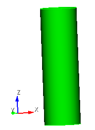
All movements and rotations are prohibited on the edges of the cylinder surface, pressure is applied to the upper circle p. The absolute value of the pressure on the outer surface of the cylinder is 1.023 MPa. Material parameters E = 200 GPa, v = 0.3.
1. Create the first circular cylinder.
On the command bar, select the module for constructing volume geometry (Mode - Geometry, Entity - Volume, Action - Create).

From the list of geometric primitives, select Cylinder.
Set the cylinder dimensions:
Height: 1;
Cross-section Type: Circular;
Radius: 0.156.
Click Apply.
2. Create a second circular cylinder.
On the command bar, select the module for constructing volume geometry (Mode - Geometry, Entity - Volume, Action - Create).
From the list of geometric primitives, select Cylinder.
Set the cylinder dimensions:
Height: 1;
Section Type: Circular;
Radius: 0.15.
Click Apply.
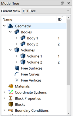
As a result, two newly created entity (Body 1 and Body 2) will be displayed in the model tree.
3. Subtract the second cylinder from the first.
On the command bar, select the module for constructing volume geometry (Mode - Geometry, Entity - Volume, Action — Boolean).
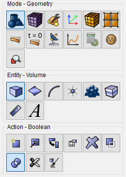
From the list of operations, select Subtract.
Set the following parameters:
A Volume ID(s): 1 (volumes from which other volumes will be deducted);
B Volume ID(s): 2 (volumes to be subtracted).
Click Apply.
As a result, only one body (Body 1) will remain in the model tree.
4. Divide the volume along the cylinder (the symmetry of the problem).
On the command bar, select the module for constructing volume geometry (Mode - Geometry, Entity - Volume, Action — Webcut).
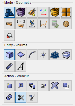
From the list of possible types of sections, select Coordinate Plane.
Set the following parameters:
Volume ID(s): 1 (the volume to be cut);
Cut: ZX plane;
Offset Value: 0.
Click Apply.
As a result, the original volume in the entity tree will be divided into two (Volume 1, Volume 3).
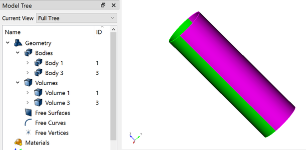
5. Print and merge the cylinder.
On the command bar, select the module for constructing volume geometry (Mode - Geometry, Entity - Volume, Action - Imprint and Merge).
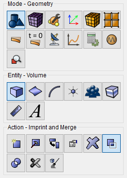
From the list of possible types of sections, select Imprint/Merge Volumes.
Set the following parameters:
Volume ID(s): 1 3.
Click Apply.
1. On the command bar, select the mesh module (Mode - Mesh, Entity - Curve, Action - Mesh).

Specify the degree of grinding of the mesh:
Select Curves: 11;
Choose the way to build the mesh: Equal;
Set the Interval flag;
Interval: 38.
Click Apply Size.
Click Mesh.
2. On the command bar, select the mesh module (Mode - Mesh, Entity - Curve, Action - Mesh).
Specify the degree of grinding of the mesh:
Select Curves: 27 18;
Choose the way to build the mesh: Equal;
Set the Interval flag;
Interval: 36.
Click Apply Size.
Click Mesh.
3. On the command bar, select the volume mesh module (Mode - Mesh, Entity - Volume, Action - Mesh).
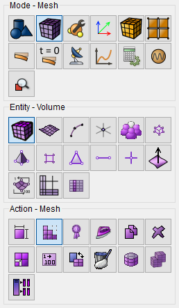
Specify the following parameters:
Select the mesh construction scheme: Map;
Select Volumes (enter their ID): 1 3 (or with the all command).
Click Apply Scheme.
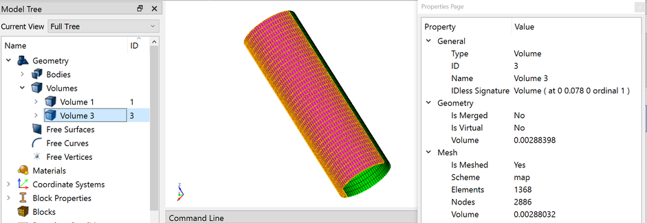
Click Mesh.
The resulting number of elements can be viewed on the properties page by clicking on the desired volume in the entity tree on the left. Also for viewing properties you can also perform the following actions:
Select the model;
Right-click on the model;
In the menu that appears, select Display information – Display information about the mesh;
Information about the mesh will appear in the command line.
1. Secure both side faces (slice) for all movements and stresses.
On the command panel, select the boundary conditions module (Mode — Boundary Conditions, Entity - Displacement, Action — Create).

Set the following parameters:
Entity List: Surface;
Entity ID(s): 21 18 12 15;
Degrees of Freedom: X, Y, Z.
Click Apply.
2. Apply pressure to the surface.
On the command panel, select the boundary conditions module (Mode — Boundary Conditions, Entity - Pressure, Action — Create).
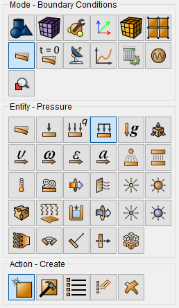
Set the following parameters:
Entity List: Surface;
Entity ID(s): 19 14;
Value: 1. 023e6 (the exponential form of the number is supported using the Latin letter "e").
Click Apply.
All the applied boundary conditions should be displayed in the entity tree on the left. In addition, the boundary conditions are editable from the tree entity. To view all the applied boundary conditions , also click Show the GU on the top panel.
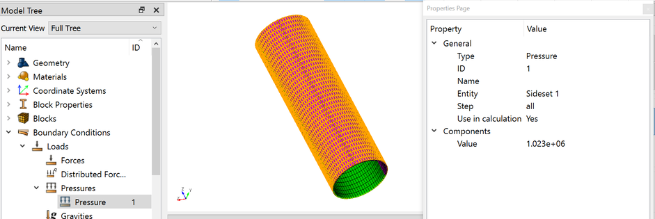
1. Create the material.
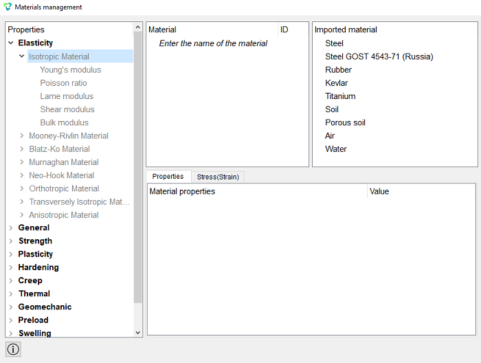
In the command bar, select the module for specifying material properties (Mode - Material, Entity - Materials Management).

In the Materials Management window that opens, double-click in the second column click on the label to enter the name of the material and write "Material 1".
Click ENTER.
Next, using the “drag&drop” technology, add the necessary characteristics from the left column to the column Material properties. In the left column choose the Elasticity – Isotropic Material. Select a characteristic with the mouse Young's modulus. Hold down the left mouse button and drag the label to Material properties. Double-click in the Value field next to Young's modulus and specify the number 2e+11. Similarly, from the Isotropic Material section, we add Poisson ratio 0.3.
Click Ok.
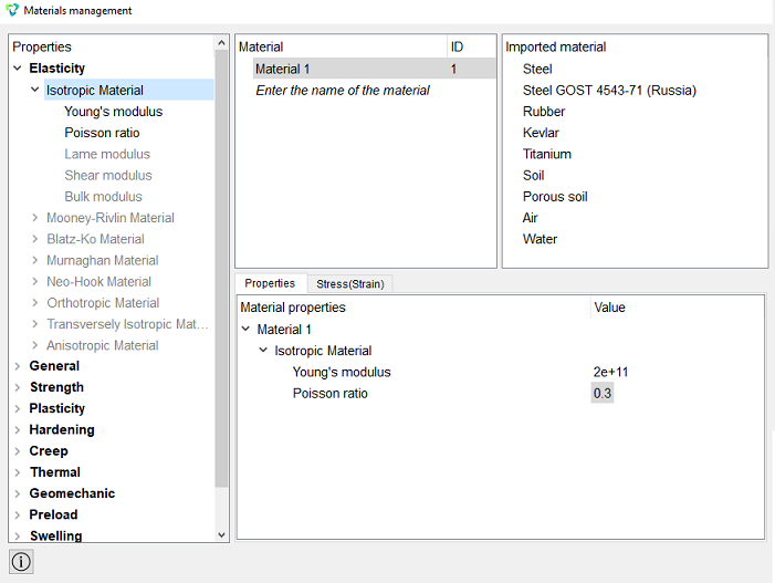
Click Apply.
Close the Materials management window.
2. Create a block of the same type of material.
On the command bar, select the block management module (Mode - Blocks, Entity - Block, Action - Add).

Set the following parameters:
Block ID: 1;
Entity List: Volume;
Entity ID(s): 1 3 (or with the all command).
Click Apply.
3. Set the block parameters.
On the command bar, select the block management module (Mode - Blocks, Entity - Block, Action - Block properties/parameters).

Set the following parameters:
Block ID(s): 1;
Category: Solid;
Material: Material 1;
Coordinate System: Global Cartesian;
Order: 1.
Click Apply.
1. Specify the type of task that you want to solve.
On the command bar, select the calculation settings module (Mode - Calculation Settings, Calculation Settings — Buckling, Buckling — General).
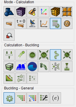
Select:
Dimension: 3D;
Type: Linear;
Number of Buckling Modes.
Click Apply.
2. In the window that opens, select the directory where the result will be saved and enter the file name.
3. In the case of a successful calculation, the console displays the message: Calculation finished successfully at "date" "time".
1. Open the file with the results. There are three ways to do that.
Click Ctrl+E.
From the main menu, select Calculation. Click Open Results.
Select Results on Command Panel (Mode - Results). Click Open results.

2. We determine the first margin coefficient
In the FidesysViewer window that appears, set the following parameters on the toolbar:
Display field: Mode 1 displacement;
Display component: Magnitude;
Display type: Surface.

On the toolbar, you can notice the displayed critical load factor.
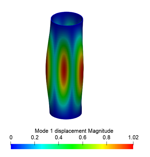
3. Next, display the first form of loss of stability for the pipe. To do this select the filter Warp By Vector on the toolbar.

On the Properties tab, set the value to 0.05 in the Scale Multiplier field.
Click Apply.
The picture below shows the first form of loss of stability.
Geometry creating, meshing, setting boundary conditions and materials can be performed using the console interface. Below is a link to the program code that allows you to perform the steps described above manual, you only need to specify the full path and name.