Search the documentation
Enter at least 2 characters
Enter at least 2 characters
 |
CAE Fidesys 9.0 Documentation |
Released: may 2021
Added support for anisotropic (Transversely isotropic and orthotropic) Material Models (alpha version)
Added the ability to set related contact when calculating the effective properties
In version 4.0 we added calculation of problems of thermal conductivity and piezoconductivity subject to the condition of bound contact.
Calculation results for problems with conditions of cyclic symmetry in the modal analysis are derived taking into account harmonic indices (nodal diameters).
In version 4.0, when creating links for each component, you can specify rigidity.
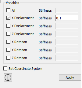
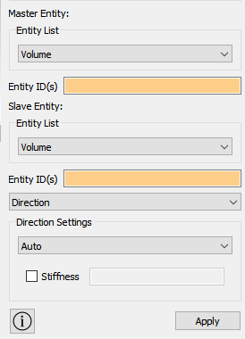
Added the ability to create links by direction. As a direction you can select the following settings: auto, vector, vector between two vertices, vector between two nodes
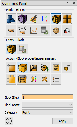
Added a new finite element consisting of one node without mechanical characteristics. An element is used, for example, to create links between its own degrees of freedom and the degrees of freedom of other elements' nodes, when creating remote loads, remote displacements. An element can be assigned to a block consisting of a vertex or a node in the section Properties / Block parameters.
The calculation of effective properties is now possible taking into account the setting of a bound contact for the model.
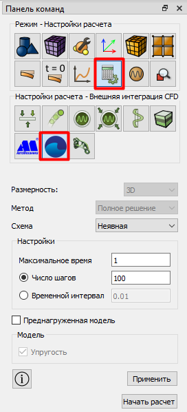
Added a new calculation option taking into account the integration of FlowVision.
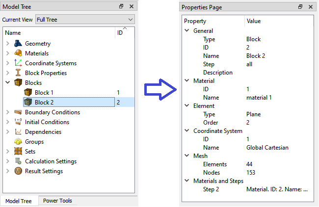
Section parameters for beams, shell elements, as well as springs and point masses can now be viewed directly in the Blocks section of the Properties tab.
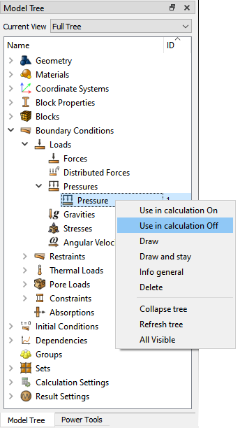
Added the ability to disable / enable boundary conditions for the calculation. Disabling / enabling is done from the context menu in the Tree.
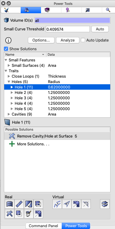
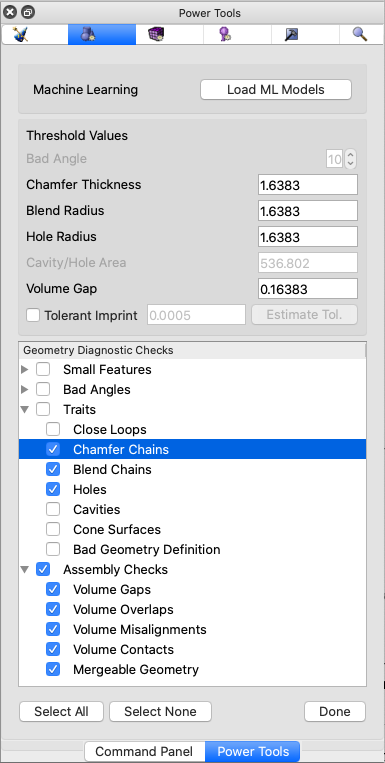
The Geometry power tool includes interactive diagnostics and solutions for defeaturing and repairing CAD models. New diagnostic tests have been added along with rapid solutions for repair. Updated and expanded diagnostics categories include Traits and Assembly Checks.
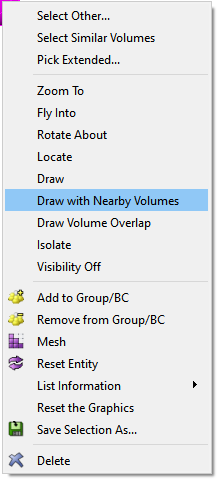
Two new options are available in the graphics window when volumes are selected:
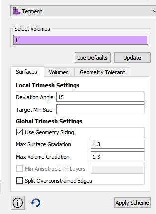
A new command panel for setting options for the tetmesh scheme is now available supporting all new local and global options for tetrahedral meshing. This panel now includes two separate tabs for setting options for surface meshing and volume mesh options. The trimesh panel has also been updated in a similar manner for setting options for the trimesh scheme.
The following commands are good for collapsing low quality tets and triangles. The user specifies a mesh entity to collapse and optionally a metric. The operation attempts to collapse the mesh entity, ensuring that the quality of surviving neighbor mesh entities does not degrade lower than the mesh entity getting collapsed. The specified metric is used to determine quality. If not specified, "Scaled Jacobian" is used. If the collapse can not be done without degrading quality, no collapse is performed. To collapse triangles, use the first two commands. Only triangle and tets can be collapsed, not faces and hexes.
Collapse Edge <id> [SCALED JACOBIAN|Aspect Ratio|Shape|Shape and Size]
Collapse Tri <id> [SCALED JACOBIAN|Aspect Ratio|Shape|Shape and Size]
Collapse Tet <id> [Altitude|Aspect Ratio|Aspect Ratio Gam|Distortion|Inradius|Jacobian|Normalized Inradius|Node Distance|SCALED JACOBIAN|Shape|Shape and Size|Timestep]
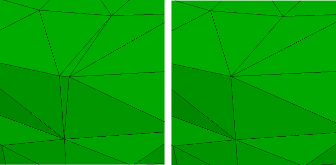
The [keep node <id>] option indicates which node to collapse the edge to. The [compress_ids] option was also added to preserve the previous behavior of compressing the mesh id space after the collapse.
Meshedit Collapse Edge <id> [keep node <id>] [compress_ids]
A new option was added to the Find Mesh Intersection command to allow naming the group created containing the intersecting mesh. If no group name is specified, the group is named 'mesh_intersect' for 3D elements and 'surf_intersect' for 2D elements.
Find Mesh Intersection {Block|Body|Surface|Volume} <id_list>> [with {Block|Body|Surface|Volume} <id_list>] [low <value=0.0001>] [high <value=0.0001>] [exhaustive] [worst <num_worst>] [draw] [log] [group <'name'>]
A new quality metric Normalized Inradius is now included as a standard option for all quality commands that affect tets and tris. It is intended to measure quality of TETRA10 and TRI6 elements, but can also measure linear (TETRA4, TRI3) elements. While most tet metrics, such as the default Shape, only take into account the 4 corner nodes of the tet, the Normalized Inradius uses the ten nodes of the tet. This is especially useful when measuring quality for a coarse tet mesh at curved surfaces where mid-edge-nodes can be projected to geometry distorting the elements. An example of using the new metric in a command to display the mesh quality is as follows:
Quality Volume All Normalized Inradius Draw Mesh
When tet meshing with TETRA10 elements or setting a block element type to TETRA10, the mid-edge nodes on the surfaces can be projected to follow the geometry. In some cases, those projections can form an invalid or poor quality element when the linear version of the elements would otherwise be acceptable. Previously, CUBIT provided the set node constraint command to control mid-edge node projections. The SMART option allows for projections only if element quality does not degrade below a quality threshold. Version 4.0 provides a new tet quality parameter and threshold parameter.
Set Node Constraint [on|off|SMART][tet quality [distortion|NORMALIZED INRADIUS]] [threshold <value=0.15>]
With the introduction of the Normalized Inradius metric in 4.0 release, the tet quality setting can use this new metric as criteria for projecting mid-edge nodes. The new threshold value permits setting of a value at which mid-edge nodes will be straightened if the quality falls below. The node constraint options can also be set in the Options or Preferences dialog under Mesh Defaults and can be saved between CAE Fidesys runs.
With 4.0 release, users have access to MeshGem's parallel tet mesher, TetraHPC. Parallel tet meshing is an option in the Tet Mesh Command panel mentioned above. Parallel tet meshing is threaded and will support up to 8 concurrent threads..
When a volume or body of a group is split in a webcut operation, the resultant pieces of the webcut will also be in the group.
Sculpt now provides an option for splitting hexes into tets using an unstructured method where each hex is subdivided into six tets. Previously only the structured approach was available which split each hex into 24 tets.
A new option for ensuring physical separation between elements of different material blocks is provided in 4.0 release. The new thicken_void option will insert elements designated as the void block material where non-void blocks would otherwise be in contact.
Using the capture = 5 option in Sculpt, mesh is fitted to the input STL. Sculpt now associates the grid edges of the reference mesh to the STL curve geometry. This is an extra level of association, in addition to the grid faces associated to the STL surface geometry. The result is better conforming of the mesh to the STL.
Color smoothing (spot optimization) in sculpt now extends smoothing out one additional layer of nodes after the first smoothing iteration, ensuring better quality.
The ability to select free surfaces (sheet bodies) has been added to the command:
Select Free [surface <id_list>] [curve <id_list>] [vertex <id_list>] [add|remove]
Added a new Tensor Glyph filter.
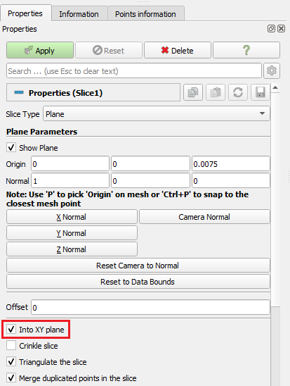
For the Slice filter, the "Into the XY plane" option has been added, which rotates and moves the section so that it ends up in the XY plane.

A Ruler tool has appeared on the toolbar to measure the distance between selected points.
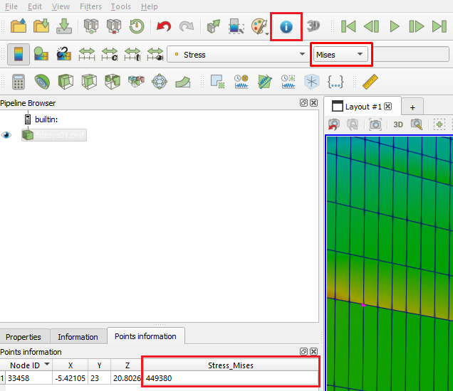
Now, for the selected point, after clicking the Points information button, only the component that is specified when displaying the field on the model will be displayed. The information is displayed in the Points information tab.