Search the documentation
Enter at least 2 characters
Enter at least 2 characters
 |
CAE Fidesys 9.0 Documentation |
Geometric volumes can be built as a hierarchy of assemblies and separate parts (details). Assemblies can be made up of parts, and also from lower level assemblies. Every assembly and every detail has name and specific description. They also have other attributes, such as material data or links to an entry in the PDM system. For additional For more information, see Metadata Attributes, as well as the following items:
A part or assembly is identified according to the path to that object, similarly path to a specific directory in the file system. The path consists of names ancestors in the object's tree structure, separated by forward slashes. For example, a part named 'p1' that is part of an assembly (an object over high-level) 'a1' is identified as the path '/a1/p1'. If the 'p2' part is part of the assembly 'a2' and the 'a2' is is part of the assembly 'a1', then as the identifier name 'p2' the path '/a1/a2/p2' is used.
More than one part can have the same name. For separation parts with the same name and the path of each part is assigned another characterizing her random number. Two parts with the same name cannot have the same and the same characteristic number. For example, two objects named 'p1' may have identifiers 'p1 instance 1' and 'p1 instance 2'.
You can include a characterizing number in the name of an object by placing it in the angular quotes after a pre-existing, possibly non-unique identifier. For example, 'p1 instance 3' is defined as the path 'p1<3>'. Other examples of using such an identification system: '/a1<1>/a2<1>/p1<3>' and '/a1/a2<1>/p1'. Assembly paths can include characterizing numbers, but only such numbers are allowed that allow avoid ambiguity. Some commands may be perceived as ambiguous paths by choosing from multiple objects randomly.
Most commands that accept an assembly path allow you to use instance option (for example, metadata list part '/a1/p1' instance 3). The instance option always refers to the last specified in a string to an object (in the example it is p1 ).
Parts and assemblies can be created with the following command:
metadata create {assembly|part} '<absolute_path>' [instance <instance>]
If you do not use the instance option, the program will assign new object a certain characterizing number. When using this option in the geometric model there should not be an object with the given name and a characterizing number, otherwise the command will generate an error.
The path must be fully qualified, specifying all the ancestors of the object being created. Ancestors that do not currently exist are automatically created.
To delete parts and assemblies, use the command:
metadata remove {part|assembly} “<path>”>
Assemblies can only be deleted if they are not related to anything. All related parts and lower level assemblies must be removed before deleting the parent assembly.
Remove all parts and assemblies that are not related to other geometries model objects, possibly with the command:
metadata clean
A part can be associated (associated) with any number of volumes, and the volume can belong to only one part. Relationships of volumes with details are displayed in the object tree and can be changed as a result of the corresponding operations using the graphical user interface. Association also done with the command:
metadata modify path “<part_path>” volume <IDs>
The volumes specified in the command will be associated with the part specified by path '<part_path>'. If there are volumes that already linked to the part, those links are retained.
To remove links, use the command:
metadata remove volume <IDs>
To change the volumes included in the part, use the command:
metadata replace part '<part_path>' volume <IDs>
After the assembly tree (object tree) is created, all assemblies of the lower levels, details and relationships between details and volumes can be displayed through the command:
metadata list tree
As a result of its execution, the names of all parts are printed in the output window. and assemblies, as well as identifiers of volumes associated with each part.
It is also possible to see all the details, their properties and relationships with volumes, using spreadsheet programs such as Microsoft Excel. This is done by creating a file with following command:
export part_list '<filename>' [overwrite]
This command writes the data as a XML file that Excel can convert to table view. After conversion data can be sorted and filtered according to selected properties details.
The export part_list command is especially useful for identifying incorrect connections of details with volumes. For this purpose, one should use filtering on the basis of is-part. This feature matters FALSE for each volume that is not associated with a part. IN as a result of such filtering, a list of all volumes that are not related to any of the details. The volume-IDs field will have the identifier of each unbound volume is shown, and in the field volume-name - his name.
A similar method can be used to identify the missing information about materials. To do this, sort and filter material details.
Metadata can be displayed and processed within a graphic user interface as part of the object tree, as shown in Figure 1:
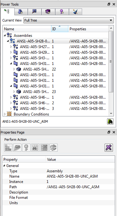
Figure. 1 - An example of a geometric tree when working with assemblies
The user can drag and drop volumes to specific locations on this tree. Selecting a particular object in the tree will display it attributes in a separate panel.