Search the documentation
Enter at least 2 characters
Enter at least 2 characters
 |
CAE Fidesys 9.0 Documentation |
The Visualization Toolkit provides a number of source and writer objects for reading and writing popular data file formats. The Visualization Toolkit also provides some of its own file formats. The main reason for creating another data file format is to provide a consistent data representation scheme for different types of data sets and to provide an easy method of transferring data between programs. Where possible, we recommend using more widely used formats. But if this is not possible, you can use the Visualization Toolkit formats described here instead. Note that these formats may not be supported by many other tools.
There are two different styles of file formats available in VTK. The simplest are the legacy serial formats, which are easy to read and write both manually and programmatically. However, these formats are less flexible than the XML-based file formats described later in this section. XML formats support random access, parallel I/O, and portable data compression, and are preferred over the sequential VTK file formats when possible.
Simple "Legacy" formats
Legacy VTK file formats consist of 5 main parts.
The first part is the version and file identifier. This part contains one line: # vtkDataFileVersionx.x. This line should be exactly as shown, except for the version number x.x, which will differ between VTK releases. (Note: The current version number is 3.0. Version 1.0 and 2.0 files are compatible with version 3.0 files).
The second part is the header. The header consists of a string of characters, terminated by the end-of-line character \n. The header contains a maximum of 256 characters. The header can be used to describe the data and include any other relevant information.
The next part is the file format. The file format describes the type of file: ASCII or binary. This line should contain one word ASCII or BINARY.
The fourth part is the structure of the dataset. The geometry part describes the geometry and topology of the dataset. This part begins with a line containing the DATASET keyword, followed by a keyword describing the type of the dataset. Then, depending on the type of the dataset, other keyword/data combinations define the actual data.
The last part describes the attributes of the dataset. This part begins with the keywords POINT_DATA or CELL_DATA, followed by an integer specifying the number of points or cells, respectively. (It does not matter whether POINT_DATA or CELL_DATA comes first.) The other keyword/data combinations then specify the actual attribute values of the dataset (i.e. scalars, vectors, tensors, normals, texture coordinates, or field data).
An overview of the file format is shown in Figure 1. The first three parts are mandatory, and the remaining two are optional. This gives you the flexibility of mixing and matching dataset attributes and geometry, either by manipulating operating system files or by using VTK filters to combine data. Keywords are case-insensitive and can be separated by spaces. Before describing the data file formats, please note the following.
dataType — one of the types bit, unsigned_char, char, unsigned_short, short, unsigned_int, int, unsigned_long, long, float или double. These keywords are used to describe the shape of the data, both for reading from a file and for constructing the corresponding internal objects. Not all data types are supported for all classes.
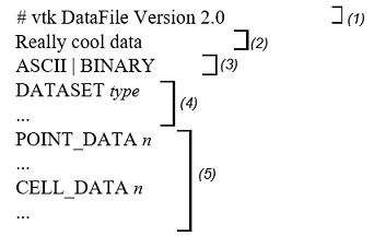
Part 1: Header.
Part 2: Name (256 characters maximum, terminated with newline \n character).
Part 3: Data type, either ASCII or BINARY.
Part 4: Geometry/Topology. Type one of: STRUCTURED_POINTS STRUCTURED_GRID UNSTRUCTURED_GRID POLYDATA RECTILINEAR_GRID FIELD.
Part 5: Dataset Attributes. The number of data elements n of each type must match the number of points or cells in the dataset. (If the type is FIELD, the point and cell data should be omitted.
Figure 1 Overview of the five data parts of the VTK file format
All key phrases are written in ASCII format, regardless of whether the file is binary or ASCII. The binary part of the file (if the file is in binary form) is the actual data; i.e., the numbers that specify the coordinates of the points, scalars, cell indices, etc.
The indices are offset by 0. Thus, the first point has a point id of 0.
If a file contains both a data attribute and a geometry/topology part, then the number of data values defined in the data attribute part must exactly match the number of points or cells defined in the geometry/topology part.
Cell types and indices are of type int.
Binary data must be placed in the file immediately after the "newline" character (\n) from the previous ASCII keyword and the parameter sequence.
The geometry/topology description must precede the data attribute description.
Binary Files. Binary files in VTK are portable between different computer systems, as long as you follow two rules. First, make sure the byte order of the data is correct, and second, make sure the length of each data type is consistent.
Most of the time, VTK manages the byte order of binary files for you. When you write a binary file on one computer and read it from another computer, the bytes representing the data will be automatically rearranged as needed. For example, binary files written on a Sun are stored in big endian order, while files on a PC are stored in little endian order. As a result, files written on a Sun workstation require byte swapping when read on a PC. (See the vtkByteSwap class for implementation details.) The VTK data files described here are written in big endian form.
However, some file formats do not explicitly define the byte order form. You will find that data read or written by external programs or the vtkVolume16Reader, vtkMCubesReader, and vtkMCubesWriter classes may have a different byte order depending on the source system. In such cases, VTK allows you to specify the byte order using methods.
SetDataByteOrderToBigEndian()
SetDataByteOrderToLittleEndian()
Another problem with binary files is that systems may use different numbers of bytes to represent an integer or other native type. For example, some 64-bit systems will represent an integer with 8 bytes, while others will represent an integer with 4 bytes. Currently, the Visualization Toolkit cannot handle transferring binary files between systems with incompatible data lengths. In this case, use ASCII file formats instead.
Dataset format. Visualization Toolkit supports five different dataset formats: structured points, structured grid, rectangular grid, unstructured grid, and polygonal data. Data with implicit topology (structured data such as vtkImageData and vtkStructuredGrid) is ordered with x increasing fastest, then y, then z. These formats are as follows.
Structured Points
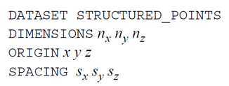
The file format supports 1D, 2D, and 3D structured point data sets. The dimensions nx, ny, nz must be greater than or equal to 1. The data interval sx, sy, sz must be greater than 0. (Note: in the version 1.0 data file, the interval was called the “aspect ratio.” ASPECT_RATIO can still be used in version 2.0 data files, but it is not recommended).
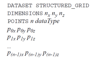
Structured Grid (Grid)
The file format supports 1D, 2D and 3D structured grid data sets. The nx, ny, nz dimensions must be greater than or equal to 1. The coordinates of the points are defined by the data in the POINTS section. It consists of x-y-z data values for each point.
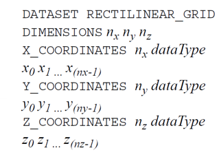
Rectilinear lattice (grid)
A rectilinear lattice defines a data set with regular topology and semiregular geometry aligned along the x-y-z coordinate axes. The geometry is defined by three lists of monotonically increasing coordinate values, one list for each of the x-y-z coordinate axes. The topology is determined.
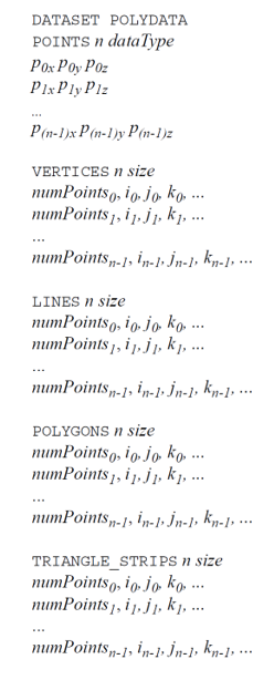
Polygon data
A polygon dataset consists of arbitrary combinations of surface graphics primitives vertices (and polyvertices), lines (and polylines), polygons (of various types), and triangle strips. Polygon data is defined by POINTS, VERTICES, LINES, POLYGONS, or TRIANGLE_STRIPS sections. The definition of POINTS is the same as we saw for structured mesh datasets. The VERTICES, LINES, POLYGONS, or TRIANGLE_STRIPS keywords define the topology of a polygon dataset. Each of these keywords requires two parameters: the number of cells n and the size of the cell list size. The size of the cell list is the total number of integer values required to represent the list (i.e., the sum of numPoints and the connectivity indices of each cell). None of the VERTICES, LINES, POLYGONS, or TRIANGLE_STRIPS keywords is required.
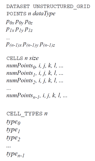
Unstructured Grid
An unstructured grid dataset consists of arbitrary combinations of any possible cell types. Unstructured grids are defined by points, cells, and cell types. The CELLS keyword requires two parameters: the number of cells n and the size of the cell list size. The size of a list of cells is the total number of integer values needed to represent the list (i.e. the sum of numPoints and the connectivity indices of each cell). The CELL_TYPES keyword requires one parameter: the number of cells n. This value must match the value specified by the CELLS keyword. The cell type data is one integer value per cell that specifies the cell type (see vtkCell.h or Figure 2).
Field
Field data is a general format without topological and geometric structure and without a defined dimensionality. Field data is usually associated with points or cells of a data set. However, if the data set type is FIELD (see Figure 1), a general VTK data object is defined. Use the format described in the next section to define a field. Also see "Working with Field Data" (from the VTK User's Guide) and the fourth example in this chapter, "Examples".
Dataset attribute format. Visualization Toolkit supports the following dataset attributes: scalars (one to four components), vectors, normals, texture coordinates (1D, 2D, and 3D), 3×3 tensors, and field data. Additionally, you can define a lookup table that uses the RGBA color specification associated with scalar data. Dataset attributes are supported for both points and cells.
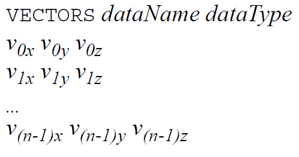
Each attribute data type has a dataName associated with it. This is a character string (without embedded spaces) used to identify a particular piece of data. The dataName is used by VTK readers to extract data. As a result, more than one attribute of the same type may be included in a file. For example, two different scalar fields defined for data set points, pressure and temperature, may be contained in a single file. (If the corresponding dataName is not specified in the VTK reader, the first data of this type is extracted from the file).
Scalars
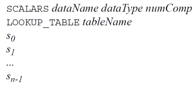
The definition of a scalar includes the specification of a lookup table. The definition of a lookup table is optional. If not specified, the default VTK table will be used (and tableName must be "default"). Also note that the numComp variable is optional - by default the number of components is one. (The numComp parameter must be in the range (1,4) inclusive; in VTK versions prior to vtk2.3 this parameter was not supported).
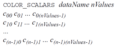
The definition of color scalars (i.e., unsigned char values directly associated with a color) depends on the number of values (nValues) per scalar. If the file format is ASCII, color scalars are defined using nValues floating-point values (float) in the range (0,1). If the file format is BINARY, the data stream consists of nValues unsigned char values per scalar value.
Lookup Table
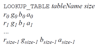
The tableName field is a character string (without embedded spaces) used to identify the lookup table. This label is used by the VTK reader to retrieve a specific table.
Each entry in the lookup table is an rgba[4] (red-green-blue-alpha) array (alpha is the opacity, where alpha = 0 is transparency). If the file format is ASCII, the lookup table values must be float values in the range (0,1). If the file format is BINARY, the data stream must consist of four unsigned char values per table entry.
Vectors
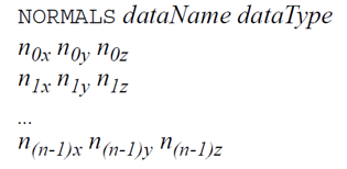
Normals
Normals are assumed to be normalized |n| = 1.
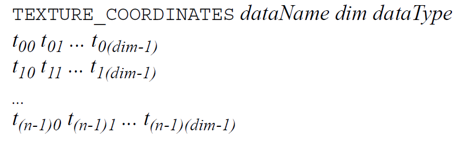
Texture Coordinates
1, 2, and 3 dimensional texture coordinates are supported.
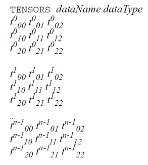
Tensors
Currently, only real symmetric tensors of size 3×3 are supported.
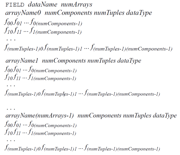
Field data
Field data is essentially an array of arrays of data. Defining field data means giving the field a name and specifying the number of arrays it contains. Then, for each array, the array name arrayName(i), the number of array components numComponents, the number of tuples in the array numTuples, and the data type dataType are defined.
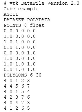
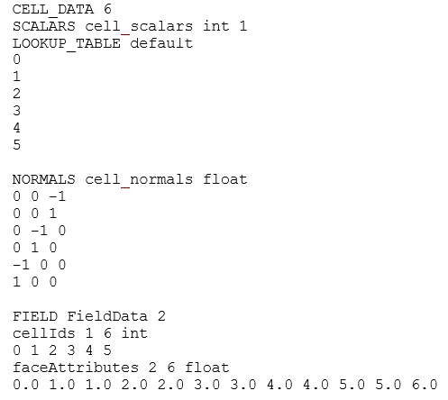
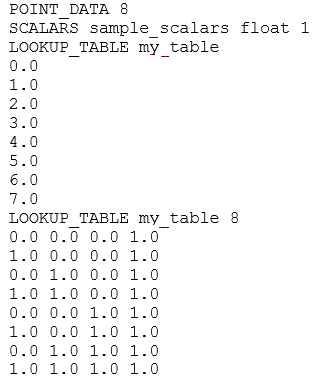
Examples. The first example is a cube represented by six polygonal faces. We define a one-component scalar, normals, and field data on the six faces. There are scalar data associated with eight vertices. A lookup table of eight colors associated with point scalars is also defined. IMPORTANT! The file must have the extension .vtk, not .VTK, otherwise a read error will occur.
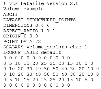
The following example is for a 3×4×5 volume. Since the lookup table is not defined, the user must either create one in VTK or the default lookup table will be used.
The third example is an unstructured mesh containing twelve of the nineteen VTK cell types (see Figure 2 and Figure 3). The file contains scalar and vector data.

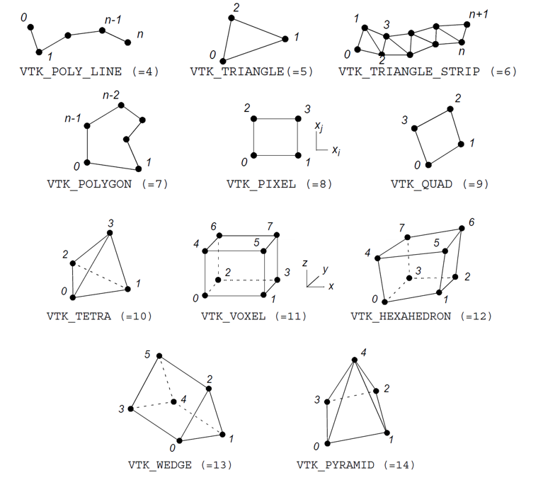
Figure 2 Linear cell types found in VTK. Use the CellType.h include file to control cell types.
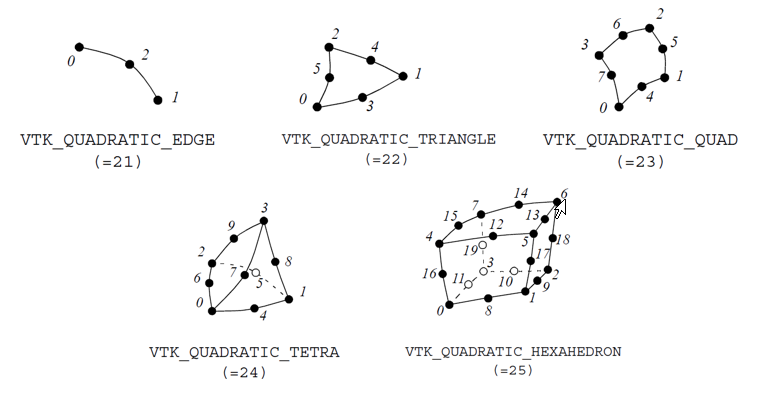
Figure 3 Nonlinear cell types found in VTK
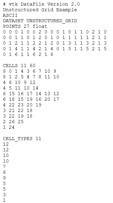
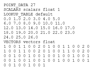
The fourth and final example is data represented as a field. You can also see "Working with Field Data" to learn how to manipulate this data. (The data file shown below can be found in its entirety in $VTK_DATA_ROOT/Data/financial.vtk).
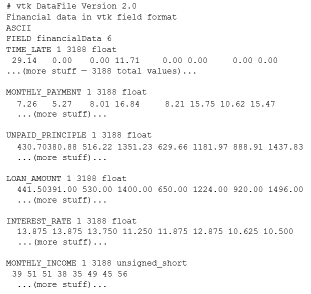
In this example, the field is represented using six arrays. Each array has one component and 3188 tuples. Five of the six arrays are of type float, and the last array is of type unsigned_short.
Additional examples are available in the data catalog.
VTK provides another set of data formats using XML syntax. Although these formats are much more complex than the original VTK format described earlier (see "Simple Legacy Formats"), they support many more features. The main motivation for their development was to simplify streaming data and parallel I/O. Some features of the format include support for compression, portable binary encoding, random access, big endian and little endian byte order, multi-file representation of fragmented data, and new file extensions for different types of VTK data sets. XML also provides many features, especially the ability to extend the file format with application-specific tags. There are two types of VTK XML data files: parallel and serial, as described below.
Serial. File types that are intended to be read and written by applications of only one process. All data is contained in a single file).
Parallel. File types that are intended to be read and written by applications with multiple processes running in parallel. The data set is divided into parts. Each process is assigned a part or set of parts to read or write. An individual part is stored in a corresponding sequential file type. A parallel file type does not actually contain any data, but instead describes the structural information and then references other sequential files that contain the data for each part.
In XML format, VTK datasets are classified into one of two categories.
Structured. The dataset is a topologically regular array of cells, such as pixels and voxels (e.g., image data) or quadrilaterals and hexagons (e.g., a structured grid) (see "Visualization Model" for more information). Rectangular subsets of the data are described by extents. Structured dataset types are vtkImageData, vtkRectilinearGrid, and vtkStructuredGrid.
Unstructured. A dataset forms a topologically irregular collection of points and cells. Subsets of data are described using parts. Unstructured dataset types are vtkPolyData and vtkUnstructuredGrid (see "Visualization Model" for more information).
By convention, each data type and file type is mapped to a specific file extension. The types and corresponding extensions are:
ImageData (.vti) — Serial vtkImageData (structured).
PolyData (.vtp) — Serial vtkPolyData (unstructured).
RectilinearGrid (.vtr) — Serial vtkRectilinearGrid (structured).
StructuredGrid (.vts) — Serial vtkStructuredGrid (structured).
UnstructuredGrid (.vtu) — Serial vtkUnstructuredGrid (unstructured).
PImageData (.pvti) — Parallel vtkImageData (structured).
PPolyData (.pvtp) — Parallel vtkPolyData (unstructured).
RectilinearGrid (.vtr) — Serial vtkRectilinearGrid (structured).
StructuredGrid (.vts) — Serial vtkStructuredGrid (structured).
UnstructuredGrid (.vtu) — Serial vtkUnstructuredGrid (unstructured).
PImageData (.pvti) — Parallel vtkImageData (structured).
PPolyData (.pvtp) — Parallel vtkPolyData (unstructured).
All VTK XML file types are valid XML documents.* The document-level element is VTKFile:

Element attributes:
type — The file type (the marked items in the previous list).
version — The file version number in "major.minor" format.
byte_order — The machine byte order in which the data is stored. This is either "BigEndian" or "LittleEndian".
compressor — Some data in the file may be compressed. Specifies the vtkDataCompressor subclass that was used to compress the data.
Inside the VTKFile element is an element whose name corresponds to the data format type (i.e. the type attribute). This element describes the topology of the data set and differs for serial and parallel formats, which are described as follows.
Sequential XML file formats. The VTKFile element contains one element whose name corresponds to the type of dataset the file describes. We call this a dataset element, which is one of ImageData, RectilinearGrid, StructuredGrid, PolyData, or UnstructuredGrid. A dataset element contains one or more Piece elements, each describing a portion of the dataset. Together, the dataset element and the Piece elements define the entire dataset.
Each dataset part must define the geometry (points and cells) of that part, along with the data associated with each point or cell. The geometry is specified differently for each dataset type, but each part of each dataset contains PointData and CellData elements that define the data for each point and cell in the part. The general structure for each sequential data set format is as follows:
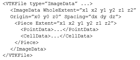
ImageData — Each part of ImageData defines its extent within the entire extent of the data set. Points and cells.
* There is one case where the file is not a valid XML document. If the AppendedData section is not base64 encoded, there is raw binary data that may violate the XML specification. This is not the default behavior, and must be explicitly enabled by the user.
are implicitly described by the extent, start, and interval. Note that the start and interval are constant for all parts, so they are specified as attributes of the XML ImageData element as follows.
RectilinearGrid — Each part of a RectilinearGrid defines
its own extent within the entire extent of the data set. Points are
described by the Coordinates element. Cells are implicitly described
by extent. 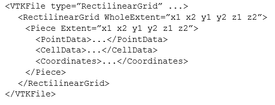
StructuredGrid — Each part of a StructuredGrid defines
its own extent within the entire extent of the data set. Points are
explicitly described by the Points element. Cells are implicitly described
by extent.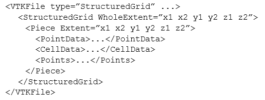
PolyData — Each PolyData part defines a set of points
and cells independently of other parts. Points are explicitly described
by the Points element. Cells are explicitly described by the Verts,
Lines, Strips, and Polys elements.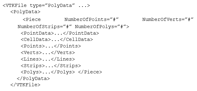
UnstructuredGrid — Each part of an UnstructuredGrid defines
a set of points and cells independently of other parts. Points are
explicitly described by the Points element. Cells are explicitly described
by the Cells element.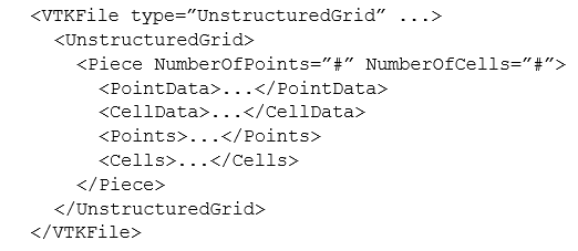
Each data set describes the data associated with its points and cells using the XML elements PointData and CellData as follows:
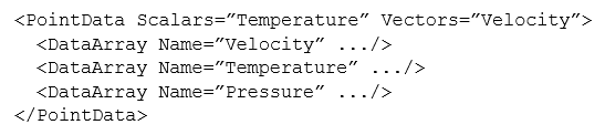
VTK allows you to associate an arbitrary number of data arrays with the points and cells of a data set. Each data array is described by a DataArray element, which, among other things, gives each array a name.
The following PointData and CellData attributes are used to specify the active arrays by name:
Scalars — The name of the active scalar array, if any.
Vectors — The name of the active vector array, if any.
Normals — The name of the active normal array, if any.
Tensors — The name of the active tensor array, if any.
TCoords — The name of the active texture coordinate array, if any.
Some data sets describe their points and cells using various combinations of the following common elements:
Points — The Points element explicitly defines the coordinates for each point individually. It contains a single DataArray element, describing an array with three components per value, each specifying the coordinates of a single point.

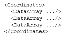
Coordinates — The Coordinates element defines the coordinates of points for the extent, specifying the ordinate along each axis for each integer value in the extent range. It contains three DataArray elements, describing the ordinates along the x-y-z axes, respectively.
Verts, Lines, Strips, and Polys — The Verts, Lines, Strips and Polys elements explicitly define cells by specifying the connectivity of the points. The cell types are implicitly known from the element type in which they are specified. Each element contains two DataArray elements. The first array specifies the connectivity of the points. All cell point lists are concatenated together. The second array specifies the offset into the connectivity array for the end of each cell.

Cells — The Cells element defines cells explicitly, specifying the connectivity of the points and the cell types. It contains three DataArray elements. The first array defines the connectivity of the points. All the lists of cell points are concatenated together. The second array defines the offset into the connectivity array for the end of each cell. The third array defines the type of each cell. (Note: the cell types are defined in Figure 2 and Figure 3).
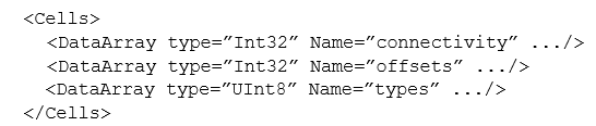
All data and geometry specifications use DataArray elements to describe their actual contents as follows:
DataArray — The DataArray element stores a sequence of values of the same type. One value may have one or more components.
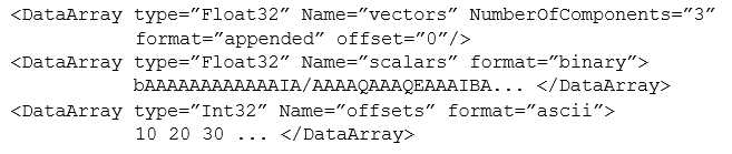
The attributes of DataArray elements are described as follows:
type — The data type of one component of the array. It is one of Int8, UInt8, Int16, UInt16, Int32, UInt32, Int64, UInt64, Float32, Float64. Note: 64-bit integer types are supported only if VTK_USE_64BIT_IDS (CMake variable — see "CMake") is enabled or the platform is 64-bit.
Name — The name of the array. This is usually a short description of the data stored in the array.
NumberOfComponents — The number of components per value in the array.
format — The way the data values themselves are stored in the file. This is "ascii", "binary", or "appended".
offset — If the format attribute is "appended", this specifies the offset from the start of the appended data section to the start of this array's data. The format attribute selects one of three ways to store the data values: format=”ascii” — The data is listed in ASCII directly inside the DataArray element. Spaces are used for separation.
format=”binary” — The data is encoded in base64 and listed contiguously inside the DataArray element. The data may also be compressed before encoding in base64. The byte order of the data corresponds to that specified in the byte_order attribute of the VTKFile element.
format=”appended” — Data is stored in the “appended data” section. Since many DataArray elements may store their data in this section, the offset attribute is used to specify where each DataArray’s data starts. This format is used by default by VTK writers.
The appended data section is stored in the AppendedData element, which is nested in the VTKFile after the dataset element:
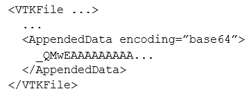
The appended data section starts with the first character after the underscore inside the AppendedData element. The underscore is not part of the data, but is always present. The data in this section is always in binary form, but may be compressed and/or base64 encoded. The byte order of the data corresponds to that specified by the byte_order attribute of the VTKFile element. The data of each DataArray is stored contiguously and is appended immediately after the data of the previous DataArray, without a separator. The offset attribute of a DataArray specifies the offset of the file position from the first character after the underscore to the beginning of its data.
Parallel File Formats. Parallel file formats do not actually store any data in the file. Instead, the data is broken up into pieces, each of which is stored in a sequential file of the same type of data set.
The VTKFile element contains a single element whose name matches the type of dataset the file describes, but with a "P" prefix. We call this a parallel dataset element, which is one of PImageData, PRectilinearGrid, PStructuredGrid, PPolyData, or PUnstructuredGrid.
The parallel dataset element and those nested within it specify the types of data arrays used to store points, point data, and cell data (the type of arrays used to store cells is fixed by VTK). The element does not actually contain any data, but instead includes a list of Piece elements that specify the source from which each piece should be read. Individual parts are stored in the corresponding serial file format. The parallel file must specify the type and structure information so that readers can update the pipeline information without actually reading the part files.
The general structure for each parallel dataset format is as follows:
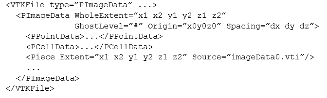
PImageData — The PImageData element defines the entire volume of the data set and the number of ghost levels by which the volumes of the individual pieces overlap. The Origin and Spacing attributes implicitly define the locations of the points. Each Piece element describes the volume of one piece and the file in which it is stored.
PRectilinearGrid — The PRectilinearGrid element defines
the entire volume of the data set and the number of ghost levels by
which the individual piece volumes overlap. The PCoordinates element
describes the type of arrays used to specify the ordinates of points
along each axis, but does not actually contain the data. Each Piece
element describes the volume of a single piece and the file in which
it is stored.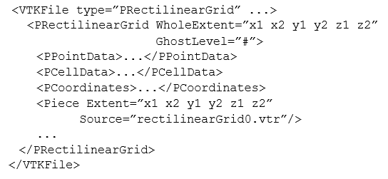
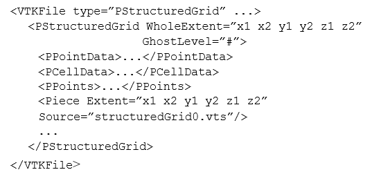
PStructuredGrid — The PStructuredGrid element defines
the entire volume of the data set and the number of ghost levels by
which the volumes in individual pieces overlap. The PPoints element
describes the type of array used to specify the locations of points,
but does not actually contain the data. Each Piece element describes
the volume of one piece and the file in which it is stored. 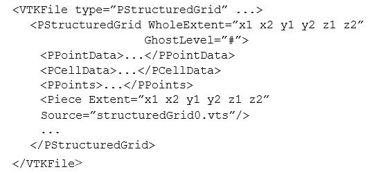
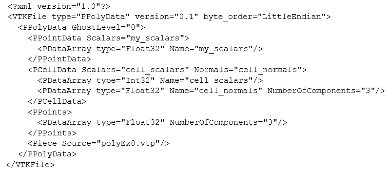
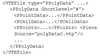
PPolyData — The PPolyData element defines the number of ghost levels on which individual pieces are mapped. The PPoints element describes the type of array used to specify point locations, but does not actually contain the data. Each Piece element defines the file in which the piece is stored.
PUnstructuredGrid — The PUnstructuredGrid element defines the number of ghost levels on which individual pieces are mapped. The PPoints element describes the type of array used to specify the locations of points, but does not actually contain the data. Each Piece element defines the file in which a piece is stored. Each data set uses PPointData and PCellData elements to describe the types of arrays of data associated with its points and cells.
Each data set uses PPointData and PCellData elements to describe the types of data arrays associated with its points and cells.
PPointData and PCellData — These elements simply mirror the PointData and CellData elements from the sequential file formats. They contain PDataArray elements that describe arrays of data, but without any actual data.
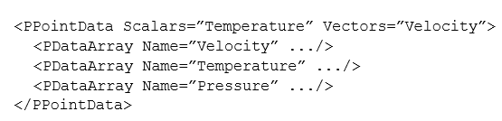
For data sets that require point specification, the following elements mirror their counterparts in the sequential file format:
PPoints — The PPoints element contains a single PDataArray element, describing an array with three components. The data array does not actually contain any data.

PCoordinates — The PCoordinates element contains three PDataArray elements that describe the arrays used to specify the ordinates for each axis. The data arrays do not actually contain any data.
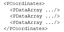
All data and geometry specifications use PDataArray elements to describe data array types:
PDataArray — The PDataArray element defines the type, Name and optionally NumberOfComponents attributes from the DataArray element. It does not contain the actual data. This can be used by readers to create an array of data in their output without having to read any actual data, which is necessary for efficient pipeline updates in some cases.

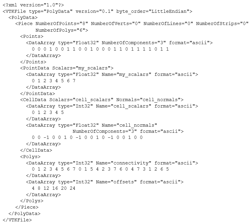
Example. Below is a complete example defining a vtkPolyData, representing a cube with some scalar data on its points and faces.